
Concept explainers
Find the slope θB&θD and deflection ΔB&ΔD at point B and D of the given beam using the moment area method.
Answer to Problem 60P
The slope θB at point B (left) of the given beam using the moment area method is 0.0033 rad_.
The deflection ΔB at point B (left) of the given beam using the moment area method is 0.39 in.(↑)_.
The slope θB at point B (right) of the given beam using the moment area method is −0.00263 rad_.
The slope θD at point D of the given beam using the moment area method is 0.0071 rad_.
The deflection ΔD at point D of the given beam using the moment area method is 0.62 in.(↓)_.
Explanation of Solution
Given information:
The Young’s modulus (E) is 30,000 ksi.
The moment of inertia of the section AB is (I) is 4,000 in.4.
The moment of inertia of the section BD is (I) is 3,000 in.4.
Calculation:
Consider flexural rigidity EI of the beam is constant.
To draw a M/EI diagram, the reactions are calculated by considering all the loads acting in the beam. The calculation of positive moment at point A is calculated by simply considering the point load of 35 kips and the reactions calculated by considering all the loads acting in the beam.
Show the free body diagram of the given beam as in Figure (1).
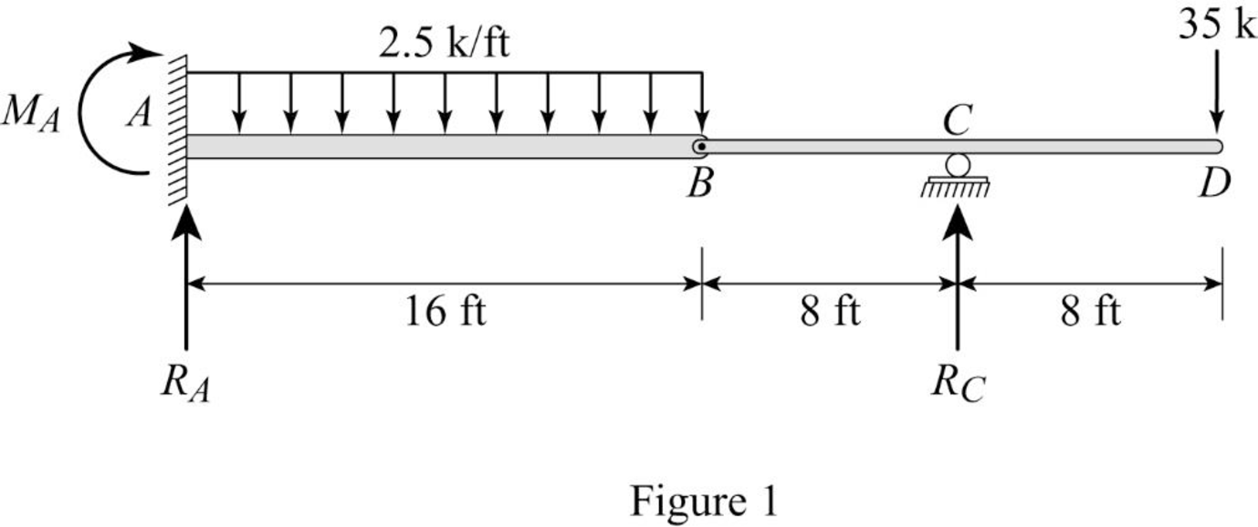
Refer Figure (1),
Consider upward is positive and downward is negative.
Consider clockwise is negative and counterclowise is positive.
Refer Figure (1),
Consider reaction at A and C as RA and RC.
Take moment about point B.
Determine the reaction at D;
RC×(8)−(35×16)=0RC=5608RC=70 kips
Determine the reaction at support A;
∑V=0RA+RC−(2.5×16)−35=0RA=75−70RA=5 kips
Determine the moment at A:
MA=−(35×32)+(70×24)−(25×16×162)=−240 kips-ft=240 kips-ft(Clockwise)
Show the reaction of the given beam as in Figure (2).
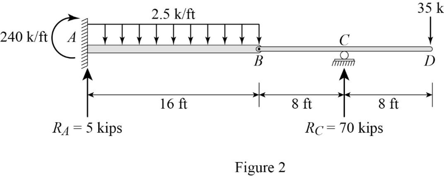
Determine the bending moment at B;
MB=70×8−35×16=560−560=0
Determine the bending moment at C;
MC=−(35×8)=−280 kips-ft
Determine the bending moment at D;
MD=−(5×32)−(70×8)−240+(2.5×16×(162+16))=−720+240+960=0
Determine the positive bending moment at A using the relation;
MA=−(35×32)+70×24=−1,120+1,680=560 kips-ft
Show the reaction and point load of the beam as in Figure (3).
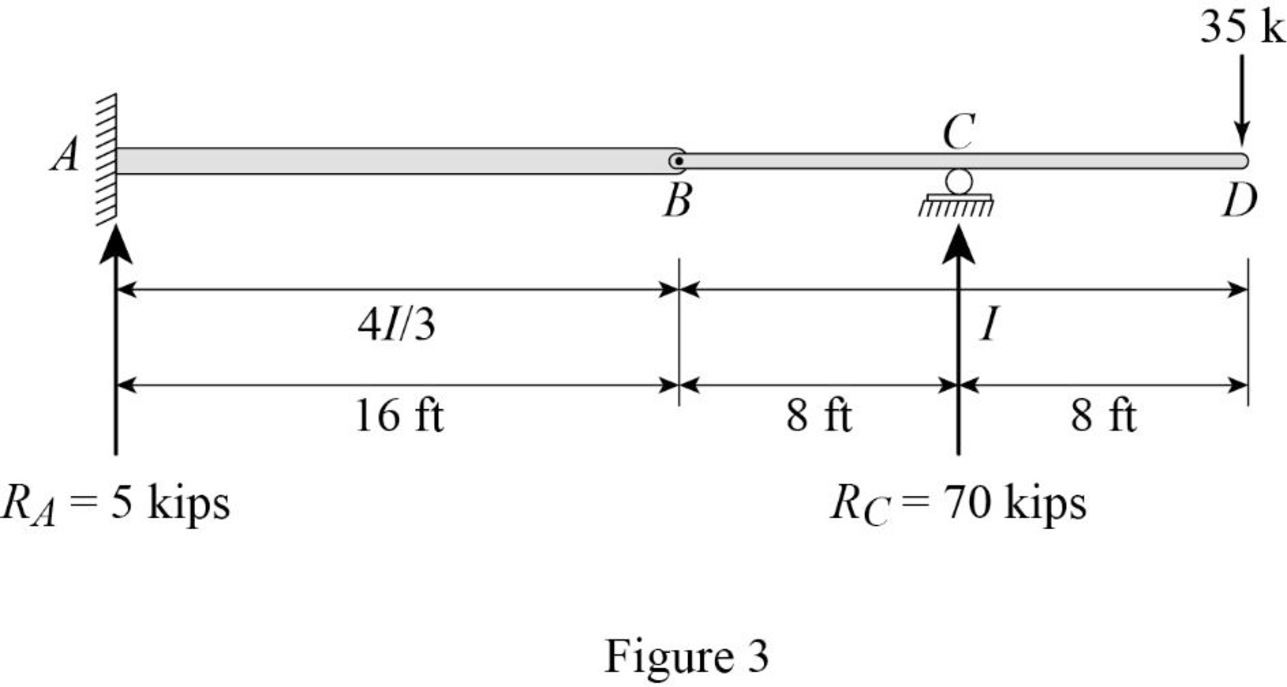
Determine the value of M/EI;
MEI=560 kips-ftEI
Substitute 4I3 for I.
MEI=560 kips-ftE(4I3)=1,680 kips-ft4EI=420 kips-ftEI
Show the M/EI diagram of the beam as in Figure (4).
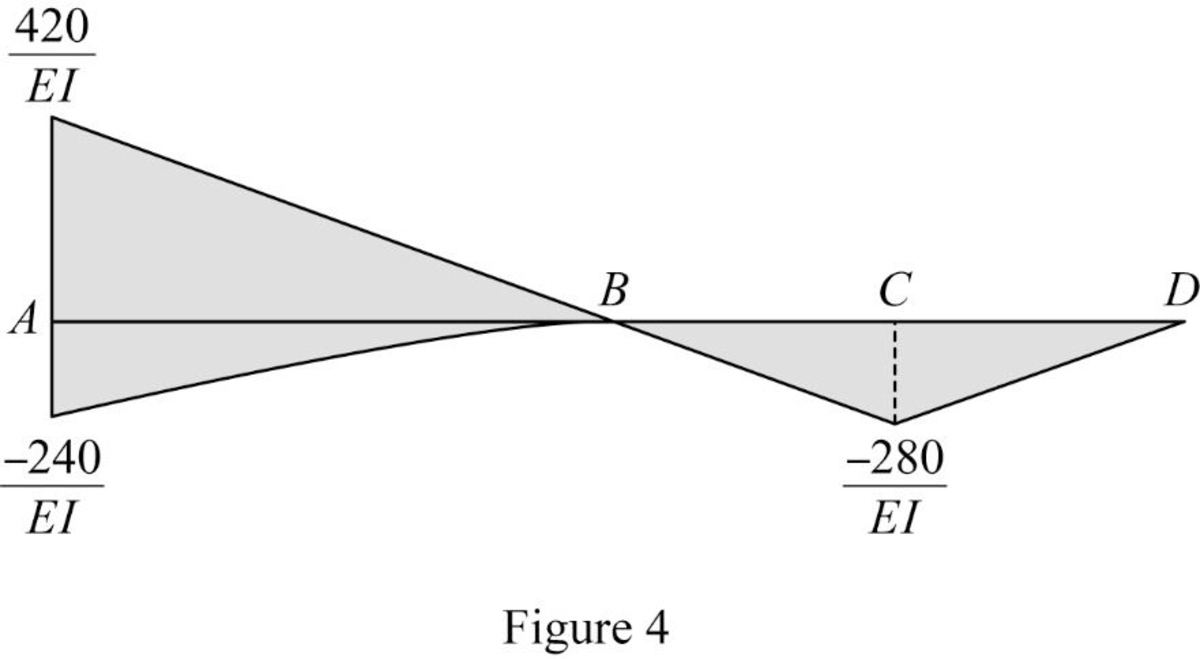
Show the conjugate beam as in Figure (5).
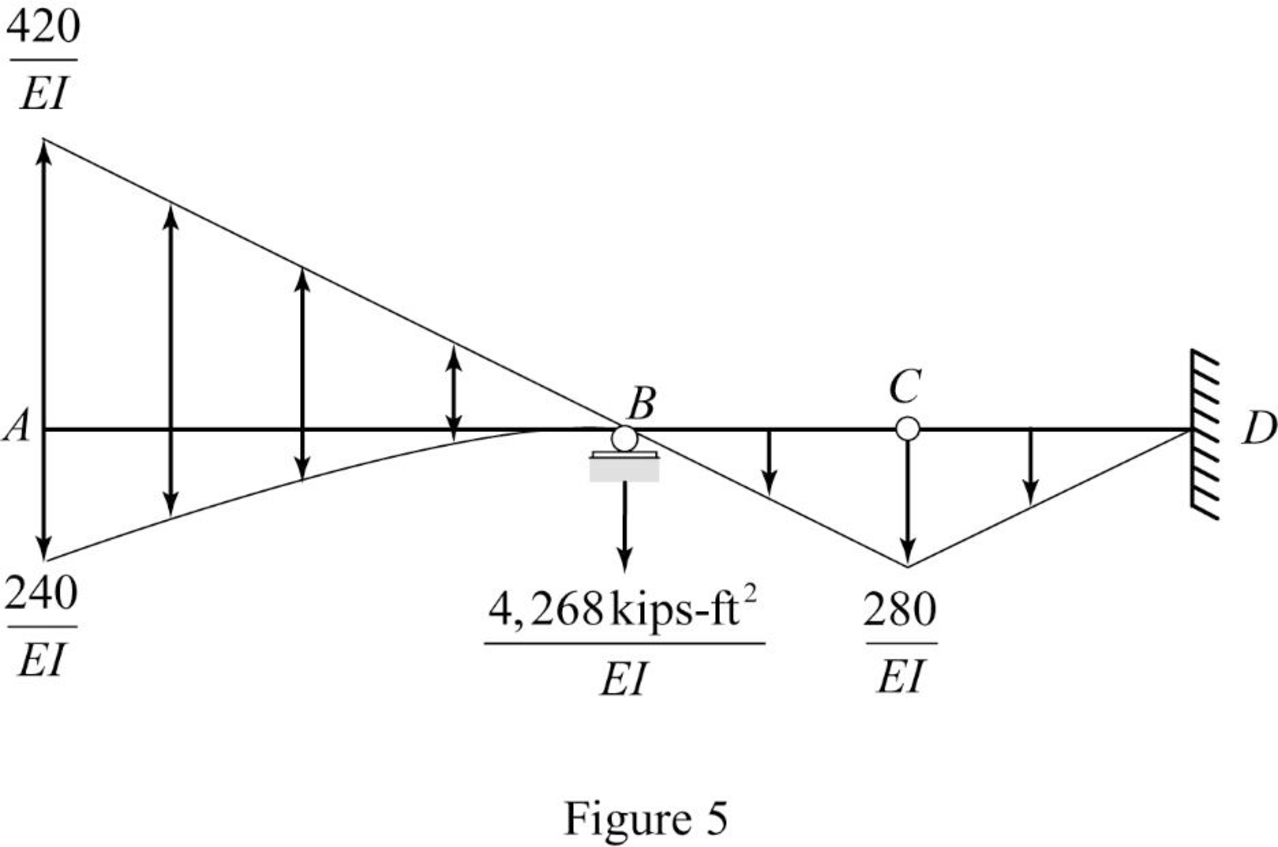
Determine the support reaction at support B;
RB×8+1EI[13×240×16×(8+34×16)−12×16×420×(8+23×16)+12×8×280×(13×8)]=0RB=25,600−62,731+2,9878EIRB=−4,268 kips-ft2EIRB=4,268 kips-ft2EI(↓)
Determine the shear force at B (left) using the relation;
SB(left)=[12×b1×h1−13×b2×h2]
Substitute 16 ft for b1, 420EI for h1, 16 ft for b2, and −240EI for h2.
SB(left)=[12×16×420EI−13×16×240EI]=2,080 kips-ft2EI
Determine the slope at B (left) using the relation;
SB(left)=2,080 kips-ft2EI
Substitute 30,000 ksi for E and 4,000 in.4 for I.
θB(left)=2,080 kips-ft2×(12 in.1 ft)230,000×3,000=0.0033 rad
Hence, the slope at B (left) is 0.0033 rad_.
Determine the slope at B (right) using the relation;
θB(right)=θB(left)−RB
Substitute 2,080 kips-ft2EI for θB(left) and 4,268 kips-ft2EI for RB.
θB(right)=2,080 kips-ft2EI−4,268 kips-ft2EI=−2,188 kips-ft2EI
Substitute 30,000 ksi for E and 4,000 in.4 for I.
θB(right)=−2,188 kips-ft2×(12 in.1 ft)230,000×4,000=−0.00263 rad
Hence, the deflection at B (right) is −0.00263 rad_.
Determine the bending moment at B using the relation;
M=[12×b1×h1×(23×b1)+13×b2×h2×(34×b2)]
Substitute 16 ft for b1, 420EI for h1, 16 ft for b2, (−240EI) for h2.
MB=[12×16×420EI×(23×16)−13×16×(240EI)×(34×16)]=35,840−15,360EI=20,480 kips-ft2EI
Determine the deflection at B using the relation;
MB=20,480 kips-ft2EI
Substitute 30,000 ksi for E and 4,000 in.4 for I.
MB=20,480 kips-ft2×(12 in.1 ft)330,000×3,000=0.39 in.(↑)
Hence, the deflection at B is 0.39 in.(↑)_.
Determine the shear force at D using the relation;
SD=[12×b1×h1+13×b2×h2+RB+12×b3×h3]
Here, b is the width and h is the height of respective triangle and parabola.
Substitute 16 ft for b1, 420EI for h1, 16 ft for b2, −240EI for h2, 4,268 kips-ft2EI for RB, 16 ft for b3, and −280EI for h3.
SD=[12×16×420EI−13×16×(240EI)−4,268−12×16×(280EI)]=3,360−1,280−4,268−2,240EI=−4,427 kips-ft2EI
Determine the slope at D using the relation;
θD=−4,427 kips-ft2EI
Substitute 30,000 ksi for E and 3,000 in.4 for I.
θD=−4,427 kips-ft2×(12 in.1 ft)230,000×3,000=−0.0071 rad
Hence, the deflection at D is −0.0071 rad_
Determine the bending moment at D using the relation;
MD=[12×b1×h1×(16+23×b1)+13×b2×h2×(16+34×b2)+(RB×16)+12×b3×h3×(24×b3)]
Substitute 16 ft for b1, 420EI for h1, 16 ft for b2, −240EI for h2, 4,268 kips-ft2EI for RB, 16 ft for b3, and −280EI for h3.
MD=[12×16×(420EI)(16+23×16)−13×16×(240EI)(16+34×16)−(4,268×16)−12×16×(280EI)×(24×16)]=89,611−35,840−68,288−17,920EI=−32,437 kips-ft3EI
Determine the deflection at D using the relation;
ΔD=−32,437 kips-ft3EI
Substitute 30,000 ksi for E and 3,000 in.4 for I.
ΔD=−32,437 kips-ft3×(12 in.1 ft)330,000×3,000=−0.62 in.=0.62 in.(↓)
Hence, the deflection at D is 0.62 in.(↓)_
Want to see more full solutions like this?
Chapter 6 Solutions
Structural Analysis


- 9.16 Two vertical parallel plates are spaced 0.012 ft apart. If the pressure decreases at a rate of 100 psf/ft in the vertical z direction in the fluid between the plates, what is the maximum fluid velocity in the Z direction? The fluid has a viscosity of 10-3 Ibf s/ft² and a specific gravity of 0.80. .arrow_forwardPlease explain steps using software.arrow_forwardPlease explain steps for using softwarearrow_forward
- Design the reinforced masonry beam in the wall shown below. The wall is to be constructed of fully grouted hollow concrete masonry units in running bond. It is to carry its own weight plus a superimposed dead load of 2.5 kips/ft and a live load of 0.8 kip/ft. Determine the width of the masonry units (by trials), and the amounts of the longitudinal and shear reinforcement required using the strength design method of TMS 402-22. Show the layout of the reinforcements with diagrams. Use fm = 2,000 psi, Grade 60(60 ksi) steel, and Type S Portland cement mortar. Assume that the centroid of the bottom rebar is 3 inches from the bottom face of the beam. ( you may assume that the unit weight of fully grouted concrete masonry is 125 lbs per cubic foot.)arrow_forward6. The easiest method to solve the beam shown in question number 14 is A. Force method B. Slope deflection method C. Moment distribution method D. Virtual work method E. Stiffness matrix method 17. The value of 8 caused by applying CW moment at A equal to 18. A. ML/2E1 B. ML/3E1 C. ML/4E1 D. ML/6EI E. None of the above For the beam shown below, the moment at A kN.m CCW. Assume P= 8 kN equals to ........ A. 20 B. 22.5 C. 25 D. 27.5 E. 30 M L A unlocked joint end pin P P P B A 1m 1m 2m 2m 19. The analysis of indeterminate non sway frames using moment distribution method does not need..... A. Finding stiffness factors of members B. Finding fix end moments C. Using compatibility equations D. Removing redundants E. Cand D 0. The frame shown is kinematically 6 kN/m indeterminate to ................ degree. A, C and D are fixed. E and B are pinned. A. First B. Second C. Third D. Fourth E. None of the above 6 m Sm 7 marrow_forward1. The moment at A using slope deflection method equals to 10 kN ..... kN. m CCW. A. 2.5 B. 5 C. 7.5 D. 10 E. None of the above 2m 2m B 10 kN + 2m + 2m 2. To solve the beam shown using slope deflection method,. ...... unknowns (s) 25 kN 15 kN/m should be selected. A. One B. Two fix C. Three D. Four E. None of the above magnitude of the rotation at B for the me shown using slope deflection method quals to El constant. A. -162/EI B. -162 El C. 40/El D. -40 El E. 0.3 radian B A 3 m 3 m -4 m- 4k/ft roller A fix 18 ft. To solve the beam shown using slope deflection method, should be fix selected as equilibrium equation (s). A. MAB+MBA = 0 B. MAB + MBA 0 and MBC=0 C. MBA+MBC = 0 D. MBA+MBC = 0 and MCB=0 E. None of the above B fix fix 9ft 20 kN/m 80 EN pin 9 m 3 m rollerarrow_forward
- Solvearrow_forward5. The number of unknowns for the frame shown using slope deflection method is... Assume A, B and D are fixed and interior hinge at C A. Two B. Four C. Six D. Eight E. None of the above 10 kN B Qc 4m A 3m + + 3m 3m 6. 7. The slope-deflection method was originally developed by Heinrich Manderla and Otto Mohr for the purpose of studying. A. secondary stresses in trusses B. secondary stresses in beams and frames C. Indeterminate beams and frames analysis D. Determinate beams and frames analysis E. None of the above In structures that have non-parallel end members, the displacement of the members will be..... A. Similar B. Different C. Proportional D. Zero E. None of the above. 8. The magnitude of the fix end moment at A 4k/ft using slope deflection method equals to pin exfix ...........k. ft. A. 25 B. -25 C. 40 D. -40 E. None of the above. A roller 15 ft- 12 f The magnitude of MBC for the frame shown in question number 3 using slope deflection method equals Assume El constant for all…arrow_forwardQ2. An isotropic rectangular slab (6 x 8) m is fixed at 3- edges and free at one edge as shown below. The reinforcement provides a positive yield moment of (10) kN.m/m and along the fixed edge a negative yield moment (m) of (14) kN.m/ m. Determine the collapse load if the slab carries a u.d.L. of (w) kN/m² including the slab own weight. W free C Gm fixed 8 m darrow_forward
- Reinforced Concrete Design 4 Second Monthly Exam 15/4/2025 Q1. A double T-concrete beam is prestressed with 2- tendons each of cross-sectional area of (600) mm² as shown below. Determine the allowable service load. Given: Span = 12 m, fse=1400 N/mm², fé= 50 N/mm², Ct = 163 mm, Cb =437 mm, I=7586 x 10 mm*. 10 KN/M * 25.00 x-500x 1500 +500 +100 163 不 -A 500 12m + 437 += 50 1 150 150 600mm 600mmarrow_forward5-18 Determine the maximum service live load that the column shown in Figure P5-18 can support if the live load is twice the dead load. (Lc)x = KxLx = 24 ft, (Lc)y = KyLy = 16 ft = 36 ksi. Solve by LRFD and ASD methods. and Fy Figure P5-18 C6×13 C6×13 PLX14X4arrow_forwardPlease answer the question in the picture, show all of you work in pictures and handwritten.arrow_forward