Concept explainers
Videos
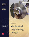
In the figure shown, shaft A, made of AISI 1020 hot-rolled steel, is welded to a fixed support and is subjected to loading by equal and opposite forces F via shaft B. A theoretical stress-concentration factor Kts of 1.6 is induced in the shaft by the
(a) For shaft A, find the factor of safety for infinite life using the modified Goodman fatigue failure criterion.
(b) Repeat part (a) using the Gerber fatigue failure criterion.
Problem 6–56

Trending nowThis is a popular solution!

Chapter 6 Solutions
EBK SHIGLEY'S MECHANICAL ENGINEERING DE
Additional Engineering Textbook Solutions
Heat and Mass Transfer: Fundamentals and Applications
DESIGN OF MACHINERY
Degarmo's Materials And Processes In Manufacturing
Applied Statics and Strength of Materials (6th Edition)
HEAT+MASS TRANSFER:FUND.+APPL.
Statics and Mechanics of Materials


- Shaft A shown below is made from AISI 1020 hot rolled steel and is welded to the wall and is subjected to loading by equal and opposite forces via shaft B. The .125 in weld produces a theoretical stress concentration factor Kts = 1.6. If Shaft A is 2 ft long (from the fixed support to shaft B) and the load F cycles from 150 to 500#, determine if the shaft has infinite fatigue life using the modified Goodman criteria. If not, determine the number of cycles to failure. in fillet Shaft A 8 -in dia F 1 in 1 in Shaft Barrow_forwardA 50 inches diameter storage tank is used to store air at an internal pressure of 625 psi with a FS = 4.5 based on ultimate strength. If the welded joints have a joint strength efficiency of 80% and the steel used to create the tank hasan equivalent strength similar to C1118,a. find a suitable plate thickness of the tank. Compare the stresses for both diametral section and longitudinal sectionb. Using the thickness solved in (a), determine the pressure to cause actual failure to the vesselarrow_forwardAn AISI 1035 CD steel tube has an OD = 45 mm and a wall thickness of 5 mm. What maximum external pressure can this tube withstand if the largest principal normal stress is not to exceed 80 % of the minimum yield strength of the material? Assume ?? = 0.arrow_forward
- A solid square rod is cantilevered at one end. The rod is 0.8 m long and supports a completely reversing transverse load at the other end of 50 kN. The material is AISI 1060 hot-rolled steel (sy = 370 MPa, Su = 680 MPa). Use a design factor of 2 and determine the dimensions of the square cross section for the following cases. Consider all possible endurance limit modifying factors. Neglect any stress concentration. a. The rod must support this load for 100 cycles.arrow_forwardmachined to dimensions. It is welded to a fix support at C and subjected to a loading by fluctuating Question 1 The assembly consists of two sections of steel shafts made off AISI 1030 Hot-rolled steeljand force E as shown below. Force F fluctuates between 100 N and 700 N. KR (both) Due to the geometry of the shafts, a fatique stress concentration factor of 1.4 and a fatigue shear stress concentration factor is 1.1 are induced. The reliability percentage is 99.9%. Shait AB hás a length of 400 mm and a diameter of 20 mm. Shaft BC has a length of 500 mm and a diameter of 30 mm. By considering the stresses at support C: 1. Calculate the mean and alternating values of the force F 2. Calculate the mean and alternating moments and torques at C 3. Calculate the endurance limit . 4. Find the factor of safety by using DE-ASME EIliptic failure theory B Le=500 mm dac 30 mm CAn=400 mm dan 20 mm 150 mm 200 mm +965 55842901 Fekry@kitechnology.org hnolegyarrow_forwardThe figure gives the cross-section of a grade 25 cast-iron pressure vessel. A total of N bolts are to be used to resist a separating force of 150 kN. (a) Determine kb, km, and C. (b) Find the number of bolts required for a load factor of 2 where the bolts may be reused when the joint is taken apart. (c) With the number of bolts obtained in part (b), determine the realized load factor for overload, the yielding factor of safety, and the load factor for joint separation. Use (SI) units as it appliesarrow_forward
- Find factor of safety if the Ultimate Stress of a ductile material is 250.94 MPa. If the material is subjected to a loading condition that generates the working stress of 151.27 MPaarrow_forwardAssume you have a 30 mm in diameter AISI 1040 steel shaft welded on a rigid surface. Forces appliedto this shaft is given below. What would be length of the shaft considering the conditions as givenbelow;− 40 Nm torque is applied throughout the shaft (torque)− 100 kg load is applied at the end point of the shaft (bending)− 250 kg load is applied to push the shaft in the compression direction (normal force)− Factor of safety should be 2arrow_forwardPLEASE ANSWER NUMBER 5.MECH 222-MECHANICS OF DEFORMABLE BODIES: PLEASE GIVE DETAILED SOLUTIONS AND CORRECT ANSWERS. I WILL REPORT TO BARTLEBY THOSE TUTORS WHO WILL GIVE INCORRECT ANSWERS.arrow_forward
- Te - Effective throat thickness well in mm = 6 sin45° Consider the following drawing in which plate 1 is welded onto plate 2 as shown for tensile and shear loading. The plates are fillet welded with a weld thickness of 6 mm as shown for a length of 150 mm. The plates have an ultimate strength of 275 MPa and the welding was done with F70 welding electrodes, which possesses an ultimate strength of 483 MPa. Consider a partial factor of safety of 1.7 for the welded joint and determine the design strength of the weld joint, both in tension (Tdw) and in shear (Vdw) due to the forces acting on it. a) Determine the design strength of the following weld in tension ( ) due to vertical forces. b) Determine the design strength of the weld in shear ( ) due to horizontal forces. Attached pic is shear equation for calculation Tension equation for calculation is: Tdw = FyLwte /Ymwarrow_forwardThe squared and grounded ends of a safety valve with 7.5 coils. The coils measure 105 mm in diameter on the outside and 17 mm wire diameter. It measures 210 mm in free length. 82 Gpa is the modulus of rigidity. Calculate the initial compression length of the wire required to maintain a boiler pressure of 1.35 Mpa on a 30 mm diameter valve seat. (Draw the diagram)arrow_forward4. Determine the design stress for bolts in a cylinder cover where the load is fluctuating due to gas pressure. The maximum load on the bolt is 50 kN and the minimum is 30 kN. The load is unpredict- able and factor of safety is 3. The surface of the bolt is hot rolled and the suface finish factor is 0.9. During a simple tension test and rotating beam test on ductile materials (40 C 8 steel annealed), the following results were obtained : Diameter of specimen =12.5 mm; Yield strength= 240 MPa; Ultimate strength= 450 MPa; Endurance limit = 180 MPa. [Ans. 65.4 MPa]arrow_forward
 Mechanics of Materials (MindTap Course List)Mechanical EngineeringISBN:9781337093347Author:Barry J. Goodno, James M. GerePublisher:Cengage Learning