
Videos
Find the current
Answer to Problem 56E
The current
Explanation of Solution
Given data:
Value of voltage
Value of resistances
Calculation:
The redrawn circuit is shown in Figure 1 as follows.
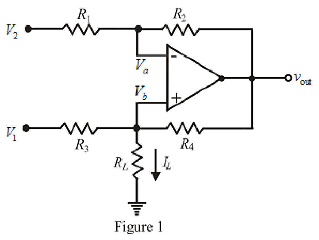
Refer to the Figure 1.
The expression for nodal analysis at node voltage
Here,
The expression for nodal analysis at node voltage
Here,
The expression for the virtual ground concept is as follows,
The expression for current
Here,
Simplify equation (1) for
Simplify the equation (2).
Substitute
Rearrange for
Simplify for
Substitute
Substitute the value of
Substitute
Conclusion:
Thus, the current
Want to see more full solutions like this?
Chapter 6 Solutions
Loose Leaf for Engineering Circuit Analysis Format: Loose-leaf


- 1. Theoretically calculate the voltage across the capacitor in the circuit of Figure 1 when t = 0 s, 5 s, 10 s, 20 s, 30 s, 40 s, and 60 s, assuming that the circuit is under DC conditions when t < 0 s and the switch is opened at t = 0 s. 2. Compare the calculated voltage at t = 20 s with the experimentally measured ∆?.arrow_forwardThe terminal voltage of a 2-H inductor is v = 10(1 – t ) V. Find the current flowing through it at t = 4s and the energy stored in it at t = 4 s. Assume i(0) = 2 A.arrow_forwardThe human body has many biological system that can be modelled mathematically. Some of these systems are open-loop others are closed loop. Your final report should consider a mathematical model of one of these systems.arrow_forward
- The following circuit has the following values:R = 40 Ω, L = 2,5 μH and C = 4nF.a)Assuming that the switch has been closed for a long time, determine the capacitor voltage and inductor current values just before opening of the key, that is, at = 0-.b)Calculate the expression for the current i(t), from the moment the switch is opened in t = 0.arrow_forwardTwo capacitors with 2.0 F and 3.0 F capacitance, respectively, are connected in parallel and subjected to total potential difference of 100 V. Find the (a) total capacitance, (b) charge stored in each capacitor, and (c) potential difference across each capacitor.arrow_forwardHow can four 100 kΩ resistors be connected so that the equivalent resistance of the four equals 250 kΩ? Sketch the arrangement, describe the resistor arrangement in words, and justify your picture by calculating the equivalent resistance. Repeat this part of the question with four 100 F capacitors and an equivalent capacitance of 75 F.arrow_forward
- What factor(s) can contribute to differences betweentheoretical (ideal) values in a circuit, and values measured inactual practice?a. Component tolerances onlyb. The sequence that components are placed in a circuitc. Measurement inaccuracy onlyd. None of the choices givene. Both component tolerances and measurement inaccuracyarrow_forwardTwo capacitors, of capacitance 3µF and 5µF, are connected as shown to batteries A and B which have EMF 4 V and 12 V respectively. What is the energy stored in each of the capacitors? Calculate also the stored energy in each capacitor when the terminals of battery A are reversed, and when the battery B is disconnected, and the points X and Y are connected together.arrow_forwardi. How can four 100 kΩ resistors be connected so that the equivalent resistance of the four equals 250 kΩ? Sketch the arrangement, describe the resistor arrangement in words, and justify your picture by calculating the equivalent resistance. ii. Repeat part i. above with four 100 F capacitors and an equivalent capacitance of 75 F.arrow_forward
- Where do we use Auxiliary Systems including SCADA in electrical engineering? Can you please explain the basic principle of those and cite some examples? the longer answer the better I'll definitely give a like :)arrow_forwardThe circuit shown in the attached image contains a voltage source with emf ε = 2.99 V, a resistor with resistance R = 135 kΩ, and a capacitor with capacitance C = 612 nF. When switch S is set to position a, the three circuit elements are in series. When the switch is in position b, the battery is excluded from the circuit. The switch is initially moved to position a, where it remains for a sufficiently long time that the capacitor is fully charged. The switch is now moved to position b. What is the magnitude of the instantaneous current, in amperes, through the resistor the instant the switch makes contact with terminal b? With time meausred the instant that switch S is closed in position b, calculate the time, in seconds, when the charge on the capacitor is one-half of its maximum value. Calculate the current through the resistor, in amperes, at time t = 155.5 ms after the switch is closed in position b.arrow_forwardA 100-pF capacitor is constructed of parallel plates of metal, each having a width W anda length L. The plates are separated by air with a distance d. Assume that L and W are bothmuch larger than d. What is the new capacitance ifa. both L and W are doubled and the other parameters are unchanged?b. the separation d is doubled and the other parameters are unchanged from their initialvalues? c. the air dielectric is replaced with oil having a relative dielectric constant of 25 and theother parameters are unchanged from their initial values ?arrow_forward
 Introductory Circuit Analysis (13th Edition)Electrical EngineeringISBN:9780133923605Author:Robert L. BoylestadPublisher:PEARSON
 Delmar's Standard Textbook Of ElectricityElectrical EngineeringISBN:9781337900348Author:Stephen L. HermanPublisher:Cengage Learning
 Programmable Logic ControllersElectrical EngineeringISBN:9780073373843Author:Frank D. PetruzellaPublisher:McGraw-Hill Education
 Fundamentals of Electric CircuitsElectrical EngineeringISBN:9780078028229Author:Charles K Alexander, Matthew SadikuPublisher:McGraw-Hill Education
 Electric Circuits. (11th Edition)Electrical EngineeringISBN:9780134746968Author:James W. Nilsson, Susan RiedelPublisher:PEARSON
 Engineering ElectromagneticsElectrical EngineeringISBN:9780078028151Author:Hayt, William H. (william Hart), Jr, BUCK, John A.Publisher:Mcgraw-hill Education,