
Videos
(a)
Find the output voltage of the circuit.
(a)
Answer to Problem 24E
The output voltage of combined circuit is
Explanation of Solution
Given data:
Combine the two circuits by eliminating the
Connect the output of circuit shown in FIGURE 6.49 to left-hand terminal of
Value of resistance
Value of input voltage of 1st op amp
Value of input voltage of 4th op amp
Calculation:
The redrawn circuit from given data is shown in Figure 1 as follows.
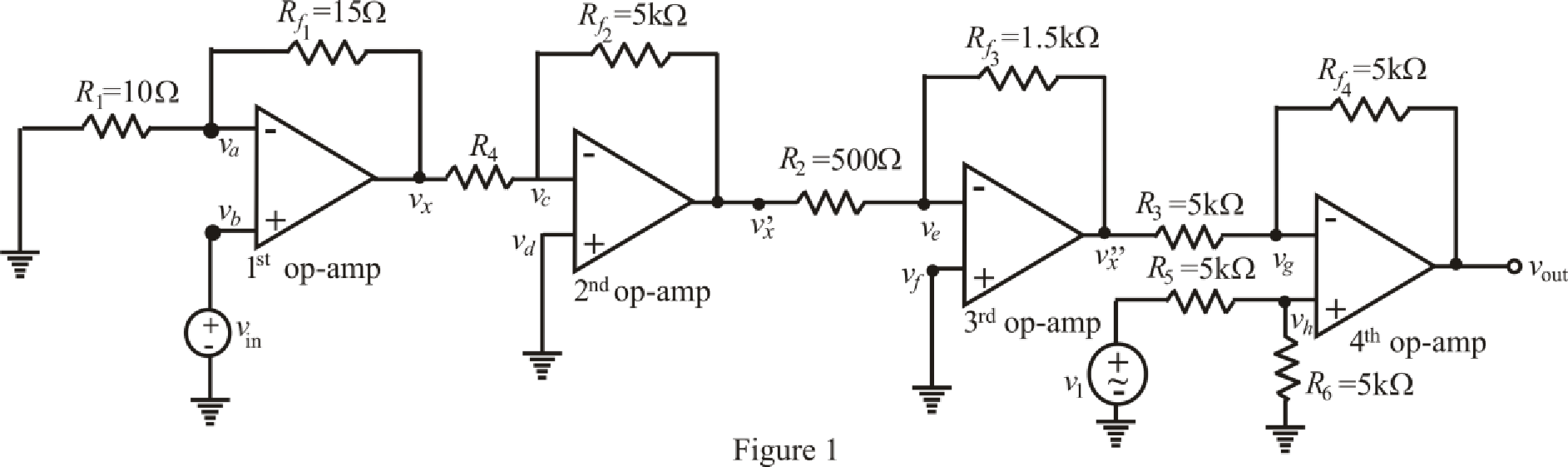
The expression for nodal analysis at node voltage
Here,
The expression for the virtual ground concept across 1st op amp is as follows.
Substitute
Rearrange for
Rearrange for
Substitute
Substitute
The expression for the nodal analysis at node voltage
Here,
The expression for the virtual ground concept across 2nd op amp is as follows,
Substitute
Rearrange for
Substitute
The expression for the nodal analysis at node voltage
Here,
The expression for the virtual ground concept across 3rd op amp is as follows.
Substitute
Rearrange for
Substitute
The expression for the nodal analysis at node voltage
Here,
The expression for the nodal analysis at node voltage
Here,
The expression for the virtual ground concept across 3rd op amp is as follows,
Simplify equation (14) for
Rearrange for
Substitute
Rearrange for
Rearrange for
Substitute
Solve for
Conclusion:
Thus, the output voltage of combined circuit is
(b)
Find the output voltage of the circuit.
(b)
Answer to Problem 24E
The output voltage of combined circuit is
Explanation of Solution
Given Data:
Value of resistance
Value of input voltage of 1st op amp
Value of input voltage of 4th op amp
Calculation:
Refer to the Figure 1,
Substitute
Substitute
Substitute
Substitute
Solve for
Conclusion:
Thus, the output voltage of combined circuit is
(c)
Find the output voltage of the circuit.
(c)
Answer to Problem 24E
The output voltage of combined circuit is
Explanation of Solution
Given Data:
Value of resistance
Value of input voltage of 1st op amp
Value of input voltage of 4th op amp
Calculation:
Refer to the Figure 1,
Substitute
Substitute
Substitute
Substitute
Solve for
Conclusion:
Thus, the output voltage of combined circuit is
Want to see more full solutions like this?
Chapter 6 Solutions
Loose Leaf for Engineering Circuit Analysis Format: Loose-leaf


- Transmitting and receiving antennas operating at 1 GHz with gains of 20 and 15 dB, respectively, are separated by a distance of 1 km. Find the power delivered to the load when the input power is 150 W. Assume the PLF = 1.arrow_forwardNot use ai pleasearrow_forwardNEED HANDWRITTEN SOLUTION DO NOT USE AI OR CHATGPTarrow_forward
- 2) Determine the voltage gain of the follower depicted in Fig. 2. Assume Is= 7 × 10-16. B = 100, VA = 5 V. Also assume the capacitors are very large. (40 points)arrow_forwardCalculate the voltage gain and I/O impedance of circuits shown in Fig. 1. Assume (60 points- each section 20 points) J Vina кат Vb J Vina кат VCC VCC VCC Vino - Vout - Vout Rs w Q2 Q2 (c) (b) Q2 = (a) - Voutarrow_forwardNot use ai please letarrow_forward
- Use PSpice to create the circuit and show the circuit along with simulation results. Also please explicitly answer the question (i.e. have the answer make sense and not in parts where there is no final answer.)arrow_forwardProblem 5 Plot the impulse response of the system shown below. Hint: This is done graphically with 4 convolutions. x[n] D y[n]< D D D D D D D D D D Darrow_forwardUse PSpice to create the circuit. Also please explicitly answer whether the load line intersects the -0.7 line at the computed point.arrow_forward
- In class, we wrote on the blackboard a byte addressable memory where each element was 2 nibbles: For example: Main memory A Address Offset Data Data Data Data Data Data Data Data Data Data Data Data Data Data Data Data 0 1 2 3 4 5 6 0 Ox10 0x00 0x02 0x2B Ox4F 0x00 0x00 0x00 0x11 0x12 0x20 0x10 0x10 0x00 OxFF Ox3E DxDD 0x00 0x00 0x00 0x00 0x00 0x00 0x00 7 0x1C 0x00 8 9 A 0x00 0x00 0x01 0x00 0x00 0x01 0x00 0x00 0x01 B с D E 0x00 0x05 0x04 0x03 0x02 0x00 Ox3D 0x00 0x1C Ox2F 0x00 Ox1F OxFF 0x03 0x02 F What is the contents of address 0x1C in main memory A for a 32 bit machine using Big Endian format? What is the contents of address 0x1C in main memory A for a 16 bit machine using Little Endian format? What is the contents of the indirect address at 0x04 in main memory A for a Big Endian 32 bit machine ((0x4))? What is the contents of 4(0x10) in main memory A for a 16 bit Little Endian machine? What is the contents of the address 16(0xC) for a 64 bit Little Endian machine?arrow_forwardProblem 4 Consider the system shown below where h₁[n] = {2,1,2} and h₂[n] = (n+1) u[n] (− means subtraction). h₂[n] x [n]- h₁[n] бел-27- h₂[n] y[n] (a) Determine the impulse response of the system and plot it for n = -3,...,6. (b) Determine graphically the response of the system to the following input. x[n] 2 4 5arrow_forwardNot use ai pleasearrow_forward
 Introductory Circuit Analysis (13th Edition)Electrical EngineeringISBN:9780133923605Author:Robert L. BoylestadPublisher:PEARSON
 Delmar's Standard Textbook Of ElectricityElectrical EngineeringISBN:9781337900348Author:Stephen L. HermanPublisher:Cengage Learning
 Programmable Logic ControllersElectrical EngineeringISBN:9780073373843Author:Frank D. PetruzellaPublisher:McGraw-Hill Education
 Fundamentals of Electric CircuitsElectrical EngineeringISBN:9780078028229Author:Charles K Alexander, Matthew SadikuPublisher:McGraw-Hill Education
 Electric Circuits. (11th Edition)Electrical EngineeringISBN:9780134746968Author:James W. Nilsson, Susan RiedelPublisher:PEARSON
 Engineering ElectromagneticsElectrical EngineeringISBN:9780078028151Author:Hayt, William H. (william Hart), Jr, BUCK, John A.Publisher:Mcgraw-hill Education,