
Concept explainers
Find the slope
Answer to Problem 33P
The slope
The deflection
The slope
The deflection
Explanation of Solution
Given information:
The Young’s modulus (E) is 29,000 ksi.
The moment of inertia (I) is
Calculation:
Consider flexural rigidity EI of the beam is constant.
Show the free body diagram of the given beam as in Figure (1).
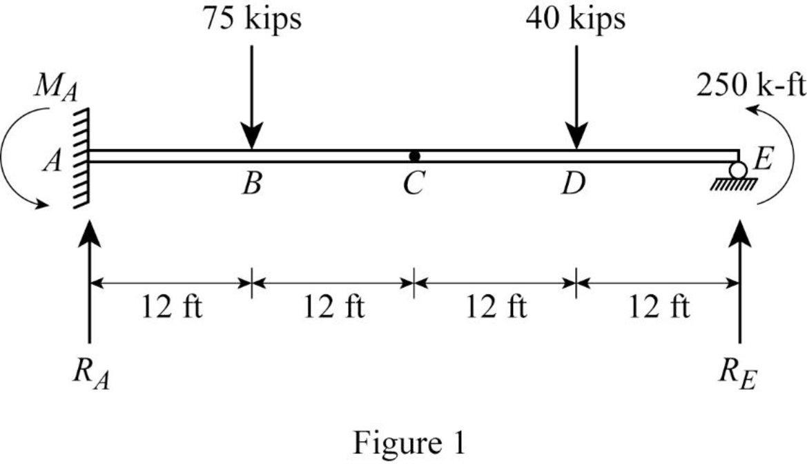
Refer Figure (1),
Consider upward is force is positive and downward force is negative.
Consider clockwise moment is negative and counterclockwise moment is positive.
Split the given beam into two sections such as AC and CE.
Consider the portion CE:
Draw the free body diagram of the portion CE as in Figure (2).
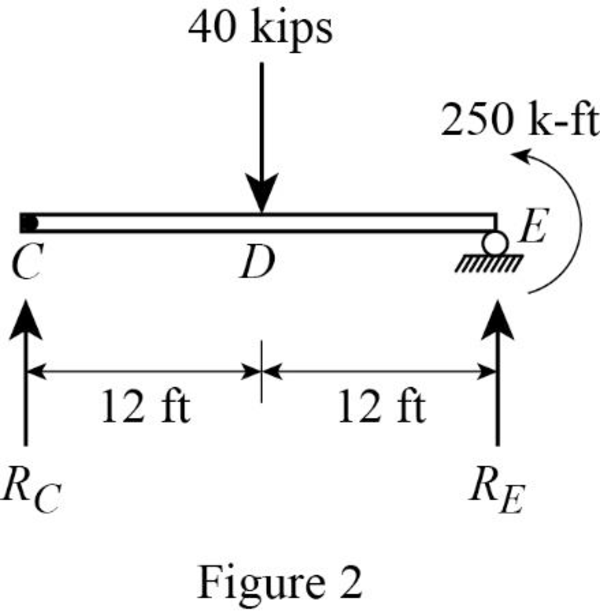
Refer Figure (2),
Consider a reaction at C and take moment about point C.
Determine the reaction at E;
Determine the reaction at support A;
Show the reaction of the given beam as in Figure (3).
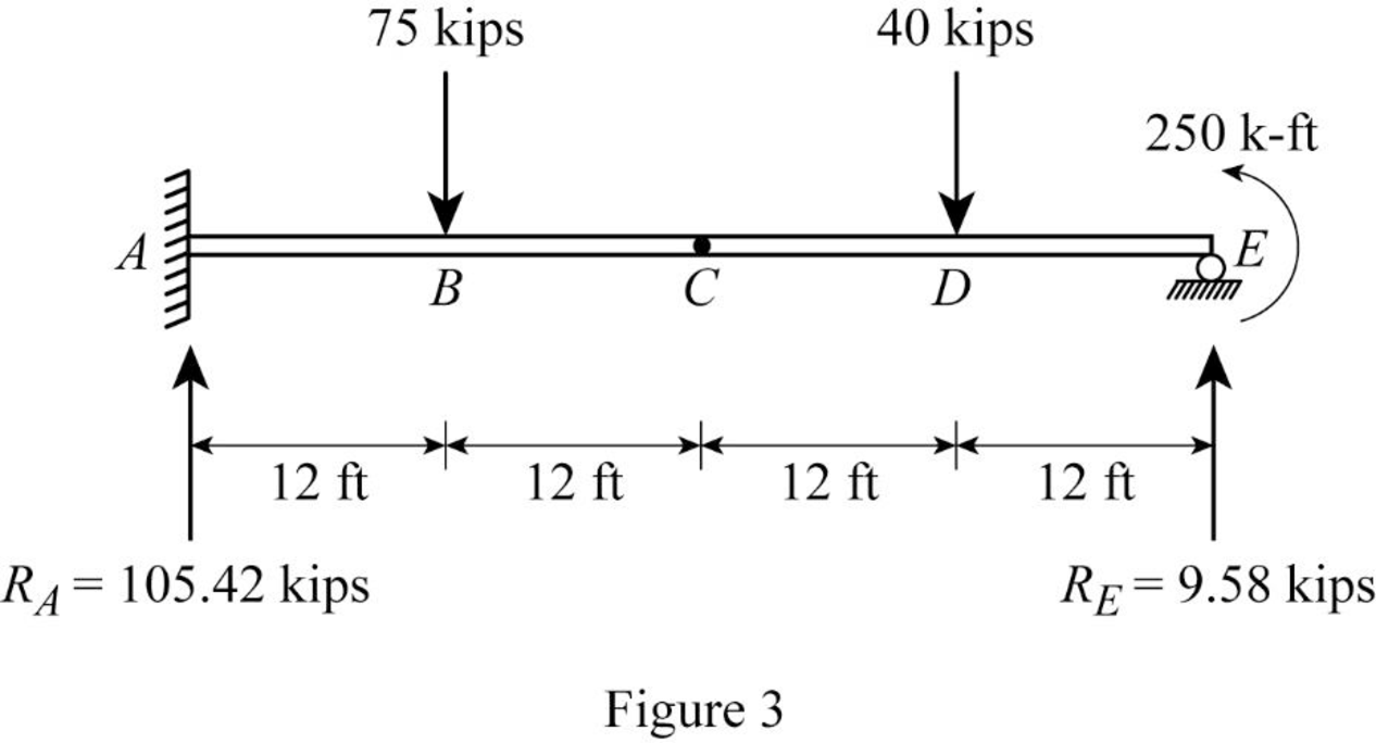
Refer Figure (3),
Determine the moment at A:
Determine the bending moment at B;
Determine the bending moment at C;
Determine the bending moment at D;
Determine the bending moment at E;
Show the
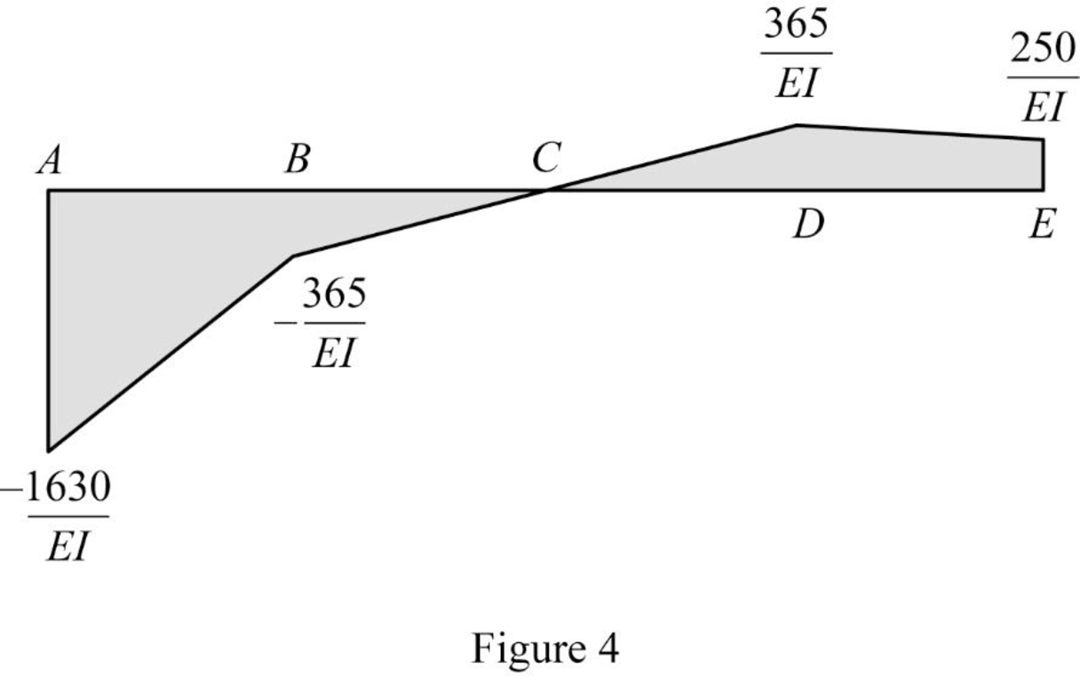
Show the elastic curve diagram as in Figure (5).
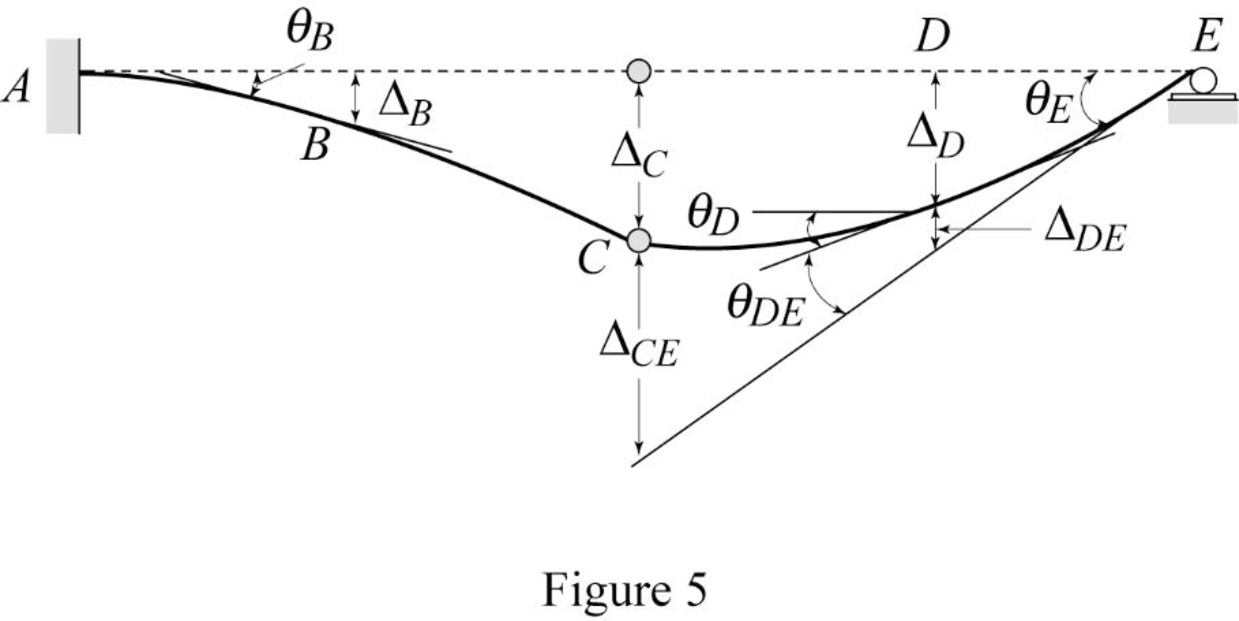
Refer Figure (4),
Determine the slope at B;
Here, b is the width and h is the height of respective triangle.
Substitute 12 ft for
Substitute 29,000 ksi for E and
Hence, the slope at B is
Determine the deflection between A and B using the relation;
Here,
Substitute 12 ft for
Substitute 29,000 ksi for E and
Hence, the deflection at B is
To determine the slope at point E, it is necessary to determine the deflection at point C and the deflection between C and E.
Determine the deflection at C and A using the relation;
Substitute 12 ft for
Determine the deflection between C and E using the relation;
Substitute 12 ft for
Determine the slope at E using the relation;
Here,
Substitute
Determine the slope between D and E using the relation;
Here, b is the width and h is the height of respective triangle.
Substitute 12 ft for
Determine the slope at D using the relation;
Substitute
Substitute 29,000 ksi for E and
Hence, the slope at D is
Determine the deflection between D and E using the relation;
Here, b is the width and h is the height of respective rectangle and triangle.
Substitute 12 ft for
Determine the deflection at D using the relation;
Substitute 12 ft for
Substitute 29,000 ksi for E and
Hence, the deflection at point D is
Want to see more full solutions like this?
Chapter 6 Solutions
Structural Analysis (MindTap Course List)
- Determine all reactions for the beam by applying the Moment Distribution Method. Provide detailed steps.Iterate until all carry over moments are less than 1 kN*m. EI is constant. ( No wrong or incomplete solutions). Thanks!arrow_forwardCalculate the bending stresses using the section shown before your name;arrow_forward4G 4G 11:33 ANSWERED Tuesday, Dec 10, 2024 ENGINEERING CIVIL-ENGINEERING Problem 6: A 2m square footing supports a 400-mm square column. The column supports an axial dead load of 1250 and an axial Ive load of 1860M. Concrete strength-21MP and steel yield strength (-225MPa Use 25mm bars and 75mm concrete cover (a) Determine the thickness based on wide beam shear (b) Determine the thickness based on punching shar 2.00m nching Expert Answer ● Steps ? ] 200m Pu d U Do 52arrow_forward
- 1. Draw the shear force and bending moment diagrams for the beam and loadings that appear in front of your name;arrow_forwardWrite the shear force and bending moment equations for the same beam and loadings;arrow_forwardAt the end of the 24th day of the project, the contractor reported that activity I has been completed and they are ready for activity J. Moreover, the contractor found that there is $3000 below the budgeted cost of the project until the completion of activity I. Using Earned Value principles (SPI & CPI): 1- Is the project over or under budget? 2- Is the project ahead or behind schedule? Activity A Duration (days) Budget ($) 2 $2,000 B 3 $15,500 C 3 $12,500 D 12 $23,000 E 4 $9,500 F 10 $18,500 G 6 $22,500 Н 2 $6,500 I 3 $4,000 J 2 $7,500 K 3 $5,500 L 1 $2,000arrow_forward
- Problem 6: A 2m square footing supports a 400-mm square column. The column supports an axial dead load of 1250kN and an axial live load of 1860kN. Concrete strength f'c 21MPa and steel yield strength fy = 275MPa. Use 25mm bars and 75mm concrete cover. (a) Determine the thickness based on wide-beam shear. (b) Determine the thickness based on punching shear. 2.00 m 400+ d c.s. punching shear 2.00 m Pu c.s. moment c.s. wide beam shear darrow_forwardA Raft foundation shown in the figure below with the following information: all columns have the same load P - 1920 kN dimensions (0.4mx0.4m), 4-140 kPa, je 35 Mpa and f 420 Mpa. Find: 1.The Foundation dimensions (L& B) 2.If d-0.55m check the effective depth d by two way action (if DL. - 3LL). 3. The steel Area (As) at points C & D for strip (AE). 15 2 m L/3 L/3 4 ☐ L/3arrow_forward3 is required to design a mat foundation for a large machine, which rests on four pedestals. The magnitude of vertical forces on each pedestal are given in the Figure below. Calculate the soil pressures at the comers of the mat. 800 KN ☐ 800 kN 700 KN 1m 8 m 700 kN 1m 2m 2.5 m 3 m 2.5marrow_forward
- USTP Buba (Cagayan de Oro | Claveria | Jasaan | Oroquieta | Panaon Vilanueva Problem 5: A rectangular footing is 3meters along the y-axis and 4m along the x-axis. The footing has a total thickness of 900mm and supports the following loads: Axial Loads: D= 1080Kn L= 480kN E = 140kN Moment about y-axis: D = 240kNm L = 60kNm E = 88kNm The height of the fill above the footing is 1.8m, unit weight of soil is 17kN/m³ and of the concrete is 23.6kN/m³. Determine the following: (a) The eccentricity of the load measured from the y-axis. (b) The maximum soil pressure due to loads. (c) The minimum required allowable soil bearing pressure. L=3m B = 4.00 m yl M, hs = 0.90 m 1.80 m + he 0.90 m +arrow_forward5. Using Area Moment Method, for the beams shown, determine the values of the slopes and deflections. ec, AA and AD. cA 20kN B A T 2m 5m 20 kN/m ப C ता 3m D E = 200,000 MPa I = 15 x 107 mm4arrow_forwardSolve it on your own. Don't use artificial intelligence find the following: a. Design strength of tension member at yielding b.Design strength of tension member at rapture c. Allowable strength of tension member at yielding d.Allowable strength of tension member at rapture e. Largest safe value for design and allowable stre of tension memberarrow_forward
