
Videos
For the op amp circuit shown in Fig. 6.39, calculate vout if (a) R1 = R2 = 100 Ω, and vin = 5 V; (b) R2 = 200R1 and vin = 1 V; (c) R1 = 4.7 kΩ, R2 = 47 kΩ, and vin = 20 sin 5t V.
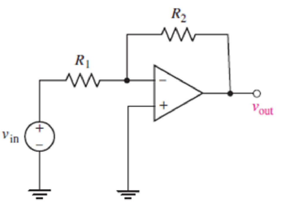
FIGURE 6.39
(a)
Find the value of
Answer to Problem 1E
The value of
Explanation of Solution
Formula used:
Refer to the FIGURE 6.39 in the Textbook.
The expression for the relation of
Here,
Calculation:
Refer to the FIGURE 6.39 in the Textbook.
Substitute
Conclusion:
Thus, the value of
(b)
Find the value of
Answer to Problem 1E
The value of
Explanation of Solution
Calculation:
Refer to the FIGURE 6.39 in the Textbook.
Substitute
Conclusion:
Thus, the value of
(c)
Find the value of
Answer to Problem 1E
The value of
Explanation of Solution
Calculation:
Refer to the FIGURE 6.39 in the TEXTBOOK.
Substitute
Conclusion:
Thus, the value of
Want to see more full solutions like this?
Chapter 6 Solutions
Loose Leaf for Engineering Circuit Analysis Format: Loose-leaf


- The circuit shown in the attached image contains a voltage source with emf ε = 2.99 V, a resistor with resistance R = 135 kΩ, and a capacitor with capacitance C = 612 nF. When switch S is set to position a, the three circuit elements are in series. When the switch is in position b, the battery is excluded from the circuit. The switch is initially moved to position a, where it remains for a sufficiently long time that the capacitor is fully charged. The switch is now moved to position b. What is the magnitude of the instantaneous current, in amperes, through the resistor the instant the switch makes contact with terminal b? With time meausred the instant that switch S is closed in position b, calculate the time, in seconds, when the charge on the capacitor is one-half of its maximum value. Calculate the current through the resistor, in amperes, at time t = 155.5 ms after the switch is closed in position b.arrow_forwardThe terminal voltage of a 2-H inductor is v = 10(1 – t ) V. Find the current flowing through it at t = 4s and the energy stored in it at t = 4 s. Assume i(0) = 2 A.arrow_forwardState which interconnections shown are permitted and which violate theconstraints imposed by the ideal sources, using the definitions of the idealindependent and dependent sources.arrow_forward
- A mesh collider a) is as accurate as the triangle count on the mesh b)is the variable optiom for complex meshes such as player characters c)is the only way to get headshots to work d)is faster than a box colliderarrow_forwardTwo capacitors, of capacitance 3µF and 5µF, are connected as shown to batteries A and B which have EMF 4 V and 12 V respectively. What is the energy stored in each of the capacitors? Calculate also the stored energy in each capacitor when the terminals of battery A are reversed, and when the battery B is disconnected, and the points X and Y are connected together.arrow_forward1. Calculate the capacitance between two parallel plates, each of which is 100 sq. Inches and 2 mm apart in air. 2. A capacitor is charged with 0.23 J of energy at a voltage of 48V. What is its capacitance? 3. A 50-uF capacitor is initially charged. Determine the initial charge of the 50-uF capacitor if the charge transferred to a 100-uF capacitor, when connected in parallel, is 200-uC.arrow_forward
- The switch has been in position 1 for a long time. At t = 0, the switch moves instantaneously to position 2. Find the value of R so that 10% of the initial energy stored in the 10mH inductor is dissipated in R in micro-second. Use KCL/KVL and refrain from using formulas.arrow_forwardDesign a circuit that amplifies a 500 mV signal originating from a computer keyboard, so that this signal can be interpreted by the digital circuits found on the motherboard.arrow_forwardDesign a monostable multivibrator to have a pulsewidth of 20 s and a recovery time of 5 s. Usethe circuit with ±5 V supplies.arrow_forward
- 1. Theoretically calculate the voltage across the capacitor in the circuit of Figure 1 when t = 0 s, 5 s, 10 s, 20 s, 30 s, 40 s, and 60 s, assuming that the circuit is under DC conditions when t < 0 s and the switch is opened at t = 0 s. 2. Compare the calculated voltage at t = 20 s with the experimentally measured ∆?.arrow_forwardfor the circuit represented by the figure, the two resistance values are R=0.752Ω and R2= 1.268 Ω respectively (a) obtain an expression for the energy stored in the capacitor, valid for all t>0; (b) Determine the setting time of the voltage labaled vcarrow_forwardHow can four 100 kΩ resistors be connected so that the equivalent resistance of the four equals 250 kΩ? Sketch the arrangement, describe the resistor arrangement in words, and justify your picture by calculating the equivalent resistance. Repeat this part of the question with four 100 F capacitors and an equivalent capacitance of 75 F.arrow_forward
 Introductory Circuit Analysis (13th Edition)Electrical EngineeringISBN:9780133923605Author:Robert L. BoylestadPublisher:PEARSON
 Delmar's Standard Textbook Of ElectricityElectrical EngineeringISBN:9781337900348Author:Stephen L. HermanPublisher:Cengage Learning
 Programmable Logic ControllersElectrical EngineeringISBN:9780073373843Author:Frank D. PetruzellaPublisher:McGraw-Hill Education
 Fundamentals of Electric CircuitsElectrical EngineeringISBN:9780078028229Author:Charles K Alexander, Matthew SadikuPublisher:McGraw-Hill Education
 Electric Circuits. (11th Edition)Electrical EngineeringISBN:9780134746968Author:James W. Nilsson, Susan RiedelPublisher:PEARSON
 Engineering ElectromagneticsElectrical EngineeringISBN:9780078028151Author:Hayt, William H. (william Hart), Jr, BUCK, John A.Publisher:Mcgraw-hill Education,