
Understanding Motor Controls
4th Edition
ISBN: 9781337798686
Author: Stephen L. Herman
Publisher: Delmar Cengage Learning
expand_more
expand_more
format_list_bulleted
Concept explainers
Videos
Textbook Question
Chapter 54, Problem 9RQ
Refer to Figure 54–9. If resistor R1 is 470 ohms and resistor R2 is 47 kilohms, what is the gain of the amplifier?
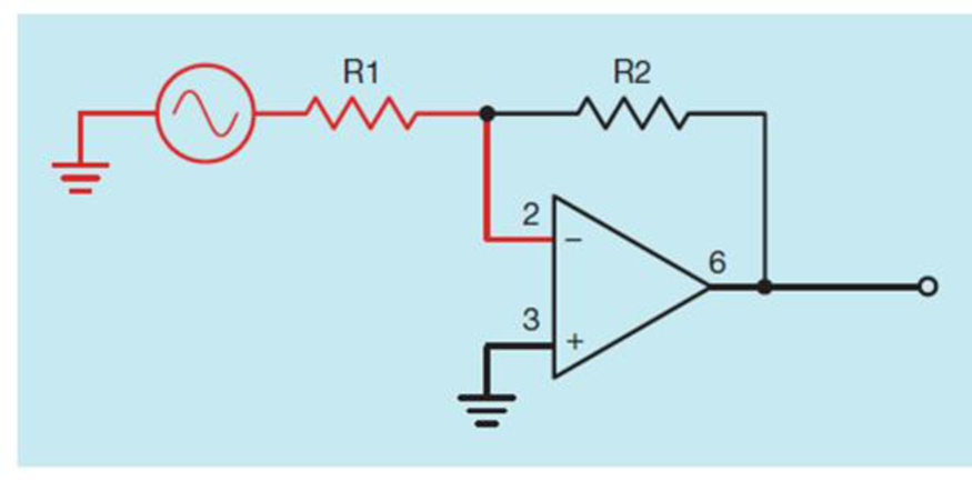
Figure 54-9 Inverting amplifier connection.
Expert Solution & Answer
Want to see the full answer?
Check out a sample textbook solution
Students have asked these similar questions
15. Find the value of R, that will produce the indicated closed-loop gain in each amplifier in Figure 12-66
Ry
W
Aj=50
ww
1.0k
Figure 12-66
10 kn
Ag=-300
Aj=8
12 k
V₁₂₁M
2.2k
(d)
Ag=-75
Given the following Resistances and Inductors in Series and Voltage Source:
R1 = 1,664 ohms
R2 = 1,999 ohms
L1 = 2 Henry
L2 = 2 Henry
Vs = 3 Volts
Frequency = 92 Hz
What is the Total Impedance (Amplitude) in ohms?
4. A circuit contains a 20-2 resistor and
an inductor with an inductance of
0.093 H. If the circuit has a frequency
of 60 Hz, what is the total impedance
of the circuit?
5. An R-L series circuit has a power
factor of 86%. By how many degrees
are the voltage and current out of
phase with each other?
6. An R-L series circuit has an apparent
power of 230 VA and a true power of
180 W. What is the reactive power?
7. The resistor in an R-L series circuit
has a voltage drop of 53 V, and the
inductor has a voltage drop of 28 V.
What is the applied voltage of the
circuit?
Chapter 54 Solutions
Understanding Motor Controls
Ch. 54 - Prob. 1RQCh. 54 - Prob. 2RQCh. 54 - Prob. 3RQCh. 54 - Prob. 4RQCh. 54 - Prob. 5RQCh. 54 - Prob. 6RQCh. 54 - Name two effects of negative feedback.Ch. 54 - Refer to Figure 548. If resistor R1 is 200 ohms...Ch. 54 - Refer to Figure 54–9. If resistor R1 is 470 ohms...Ch. 54 - What is the purpose of the hysteresis loop when...
Knowledge Booster


Learn more about
Need a deep-dive on the concept behind this application? Look no further. Learn more about this topic, mechanical-engineering and related others by exploring similar questions and additional content below.Similar questions
- Refer to Figure 548. If resistor R1 is 200 ohms and resistor R2 is 10 kilohms, what is the gain of the amplifier? Figure 548 Noninverting amplifier connection.arrow_forwardThe sinusoidal current waveform having the maximum value of 75 A, then the R.M.S value isarrow_forward9. Identify the resistance of 5 point the Following Five Band Resistor * 60M Ohms +5% O 4000K Ohms +5% O 2000K Ohm +5%arrow_forward
- If the impedance Z1 = 10 +j10 and the impedance Z2 = 10 - j0 are connected in series, the equivalent impedance would be: O A. 20-j10 ohms O B. 20+ j20 ohms O C. None of the other choices are correct O D. 20 ohms O E. 20+ j 10 ohmsarrow_forwardDraw the output waveform for the given circuit diagram with proper values and also mention the name of the circuit. The input waveform Vi is having a peak-to-peak value of 13 V and the bias voltage is 4 V. Assume diode to be germanium. R Vị Vo Maximum value of output waveform Minimum voltage of output waveformarrow_forward17. If a signal voltage of 10 mVrms is applied to each amplifier in Figure 12-67, what are the output voltages and what is their phase relationship with inputs? 18. Determine the approximate values for each of the following quantities in Figure 12-68 LO ET Spie 2210 W 22 k Figure 12-68 a. In b. l c. Vout d. closed-loop gainarrow_forward
- When n-type material is sandwiched between two p-type materials such type of transistor is called: ppn nnp npn pnparrow_forward9. Figure 12-62 shows the output voltage of an op-amp in response to a step input. What is the slew rate? A 15μs +12V- -12V- Figure 12-62 10. How long does it take the output voltage of an op-amp to go from -10 V to +10 V if the slew rate is 0.5 V/μS?arrow_forwardFor the circuit shown below, calculate the Thévenin's equivalent circuit to the left of the resistor R. R1 10Ω 10Ω E 10 V R3 R2 10Ω O . Rth= 15 0, Van = 5 V O b. Rth= 30 0, Vah = 10 V O c. Rth= 15 0, Veh = 10 V O d. Rh= 30 Q, Vah = 5 Varrow_forward
- A balanced positive-sequence wye-connected 60-Hz three-phase source has line-to-line voltages of VL = 440 V rms. This source is connected to a balanced wye-connected load. Each phase of the load consists of a 0.5-H inductance in series with a 50-? resistance. Assume that the phase of Van is zero. A) Find the line-to-neutral voltage phasor Van. Enter your answer using polar notation. Express argument in degrees. B) Find the line-to-neutral voltage phasor Vbn. Enter your answer using polar notation. Express argument in degrees. C) Find the line-to-neutral voltage phasor Vcn. Enter your answer using polar notation. Express argument in degrees. D) Find the line-to-line voltage phasor Vab. Enter your answer using polar notation. Express argument in degrees.arrow_forwardThe sensing element which converts the mechanical signal into electrical signal is known as secondar sensing element. Select one: True Falsearrow_forwardA transistor has a DC Beta of 250 and a base current, IB, of 20 microA. The collector current, IC, equals * 5 microamperes 500 microamperes 5 milliamperes 50 milliamperesarrow_forward
arrow_back_ios
SEE MORE QUESTIONS
arrow_forward_ios
Recommended textbooks for you
 Understanding Motor ControlsMechanical EngineeringISBN:9781337798686Author:Stephen L. HermanPublisher:Delmar Cengage Learning
 Electrical Transformers and Rotating MachinesMechanical EngineeringISBN:9781305494817Author:Stephen L. HermanPublisher:Cengage Learning
 Refrigeration and Air Conditioning Technology (Mi...Mechanical EngineeringISBN:9781305578296Author:John Tomczyk, Eugene Silberstein, Bill Whitman, Bill JohnsonPublisher:Cengage Learning
Understanding Motor Controls
Mechanical Engineering
ISBN:9781337798686
Author:Stephen L. Herman
Publisher:Delmar Cengage Learning
Electrical Transformers and Rotating Machines
Mechanical Engineering
ISBN:9781305494817
Author:Stephen L. Herman
Publisher:Cengage Learning
Refrigeration and Air Conditioning Technology (Mi...
Mechanical Engineering
ISBN:9781305578296
Author:John Tomczyk, Eugene Silberstein, Bill Whitman, Bill Johnson
Publisher:Cengage Learning
Ch 2 - 2.2.2 Forced Undamped Oscillation; Author: Benjamin Drew;https://www.youtube.com/watch?v=6Tb7Rx-bCWE;License: Standard youtube license