
Understanding Motor Controls
4th Edition
ISBN: 9781337798686
Author: Stephen L. Herman
Publisher: Delmar Cengage Learning
expand_more
expand_more
format_list_bulleted
Concept explainers
Videos
Textbook Question
Chapter 54, Problem 8RQ
Refer to Figure 54–8. If resistor R1 is 200 ohms and resistor R2 is 10 kilohms, what is the gain of the amplifier?
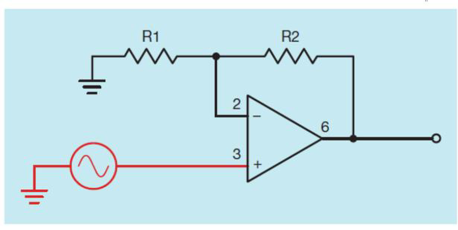
Figure 54–8 Noninverting amplifier connection.
Expert Solution & Answer
Want to see the full answer?
Check out a sample textbook solution
Students have asked these similar questions
4. A circuit contains a 20-2 resistor and
an inductor with an inductance of
0.093 H. If the circuit has a frequency
of 60 Hz, what is the total impedance
of the circuit?
5. An R-L series circuit has a power
factor of 86%. By how many degrees
are the voltage and current out of
phase with each other?
6. An R-L series circuit has an apparent
power of 230 VA and a true power of
180 W. What is the reactive power?
7. The resistor in an R-L series circuit
has a voltage drop of 53 V, and the
inductor has a voltage drop of 28 V.
What is the applied voltage of the
circuit?
9. Identify the resistance of
5 point
the Following Five Band
Resistor *
60M Ohms +5%
O 4000K Ohms +5%
O 2000K Ohm +5%
If the impedance Z1 = 10 +j10 and the impedance Z2 = 10 - j0 are connected in series, the equivalent impedance
would be:
O A. 20-j10 ohms
O B. 20+ j20 ohms
O C. None of the other choices are correct
O D. 20 ohms
O E. 20+ j 10 ohms
Chapter 54 Solutions
Understanding Motor Controls
Ch. 54 - Prob. 1RQCh. 54 - Prob. 2RQCh. 54 - Prob. 3RQCh. 54 - Prob. 4RQCh. 54 - Prob. 5RQCh. 54 - Prob. 6RQCh. 54 - Name two effects of negative feedback.Ch. 54 - Refer to Figure 548. If resistor R1 is 200 ohms...Ch. 54 - Refer to Figure 54–9. If resistor R1 is 470 ohms...Ch. 54 - What is the purpose of the hysteresis loop when...
Knowledge Booster


Learn more about
Need a deep-dive on the concept behind this application? Look no further. Learn more about this topic, mechanical-engineering and related others by exploring similar questions and additional content below.Similar questions
- For the circuit shown below, calculate the Thévenin's equivalent circuit to the left of the resistor R. R1 10Ω 10Ω E 10 V R3 R2 10Ω O . Rth= 15 0, Van = 5 V O b. Rth= 30 0, Vah = 10 V O c. Rth= 15 0, Veh = 10 V O d. Rh= 30 Q, Vah = 5 Varrow_forwardIn the experiment No.4, the core loss component current is given by_ Ic Sinôo lo Sindo lc Cos&o lo Cosoarrow_forwardQ4 Find V1 and V2 in the circuit shown below. Also calculate 11 and 12, and the power dissipated in the 120 And 400 resistors. 15 V 12 Ω ww + 60 ww www. 10 Ω + www iz 40 Ωarrow_forward
- 15. Find the value of R, that will produce the indicated closed-loop gain in each amplifier in Figure 12-66 Ry W Aj=50 ww 1.0k Figure 12-66 10 kn Ag=-300 Aj=8 12 k V₁₂₁M 2.2k (d) Ag=-75arrow_forwardGiven the following Resistances and Inductors in Series and Voltage Source: R1 = 1,664 ohms R2 = 1,999 ohms L1 = 2 Henry L2 = 2 Henry Vs = 3 Volts Frequency = 92 Hz What is the Total Impedance (Amplitude) in ohms?arrow_forwardWhen n-type material is sandwiched between two p-type materials such type of transistor is called: ppn nnp npn pnparrow_forward
- A transistor has a DC Beta of 250 and a base current, IB, of 20 microA. The collector current, IC, equals * 5 microamperes 500 microamperes 5 milliamperes 50 milliamperesarrow_forwardDetermine the reverse voltage and reverse current for the diode for each diode models. Also, find the voltage across the limiting resistor in each case. Assume IR=1UA. VBIAS + = 5 V RLIMIT W 1.0 ΚΩ ₁arrow_forwardCalculate the Resistance , if the RTD temperature is 2506.8 oC and Sensitivity is 9.6 oC/ohmarrow_forward
- 1. A moving coil voltmeter with a resistance of 150 ohms gives a full scale deflection with a potential difference of 100 mV. The coil has an effective depth of 100 mm and a width of 145 mm. The permanent magnetic field has the flux of 45 mWeb with an area of 3mm, and 50 mm. Controlling torque exerted by the spring is 50 x 10-6 Newton-meter. Calculate the number of tums in the moving coil, and also calculate the deflection of the pointer. [2M]arrow_forwardThree inductors are connected in parallel. Inductor 1 has an inductance of 0.06 H; inductor 2 has an inductance of 0.05 H; and inductor 3 has an inductance of 0.1 H. What is the total inductance of this circuit?arrow_forwardHow many degrees are the current and voltage out of phase with each other in a pure resistive circuit?arrow_forward
arrow_back_ios
SEE MORE QUESTIONS
arrow_forward_ios
Recommended textbooks for you
 Understanding Motor ControlsMechanical EngineeringISBN:9781337798686Author:Stephen L. HermanPublisher:Delmar Cengage Learning
 Electrical Transformers and Rotating MachinesMechanical EngineeringISBN:9781305494817Author:Stephen L. HermanPublisher:Cengage Learning
 Refrigeration and Air Conditioning Technology (Mi...Mechanical EngineeringISBN:9781305578296Author:John Tomczyk, Eugene Silberstein, Bill Whitman, Bill JohnsonPublisher:Cengage Learning
Understanding Motor Controls
Mechanical Engineering
ISBN:9781337798686
Author:Stephen L. Herman
Publisher:Delmar Cengage Learning
Electrical Transformers and Rotating Machines
Mechanical Engineering
ISBN:9781305494817
Author:Stephen L. Herman
Publisher:Cengage Learning
Refrigeration and Air Conditioning Technology (Mi...
Mechanical Engineering
ISBN:9781305578296
Author:John Tomczyk, Eugene Silberstein, Bill Whitman, Bill Johnson
Publisher:Cengage Learning
Ch 2 - 2.2.2 Forced Undamped Oscillation; Author: Benjamin Drew;https://www.youtube.com/watch?v=6Tb7Rx-bCWE;License: Standard youtube license