
Vector Mechanics for Engineers: Statics, 11th Edition
11th Edition
ISBN: 9780077687304
Author: Ferdinand P. Beer, E. Russell Johnston Jr., David Mazurek
Publisher: McGraw-Hill Education
expand_more
expand_more
format_list_bulleted
Concept explainers
Videos
Textbook Question
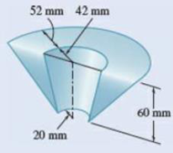
Chapter 5.2, Problem 5.61P
Determine the volume and total surface area of the bushing shown.
Fig. P5.61
Expert Solution & Answer
Want to see the full answer?
Check out a sample textbook solution
Students have asked these similar questions
Locate the centroid of the plane area shown.
y
30 mm
300 mm
30 mm
240 mm
Fig. P5.1
Locate the centroid of the plane area shown.
G
1 = 72 mm
2= 120 mm
Fig. P5.12
Problem 5.64
2.5 k/ft
Draw the shear, bending moment, and axial
force diagrams and the qualitative deflected
shape for the frame shown.
12 ft
30 k
12 ft
D
20 ft
FIG. P5.64
Chapter 5 Solutions
Vector Mechanics for Engineers: Statics, 11th Edition
Ch. 5.1 - 5.1 through 5.9 Locate the centroid of the plane...Ch. 5.1 - 5.1 through 5.9 Locate the centroid of the plane...Ch. 5.1 - 5.1 through 5.9 Locate the centroid of the plane...Ch. 5.1 - Locate the centroid of the plane area shown.Ch. 5.1 - 5.1 through 5.9 Locate the centroid of the plane...Ch. 5.1 - Locate the centroid of the plane area shown.Ch. 5.1 - 5.1 through 5.9 Locate the centroid of the plane...Ch. 5.1 - Locate the centroid of the plane area shown.Ch. 5.1 - Locate the centroid of the plane area shown.Ch. 5.1 - Locate the centroid of the plane area shown.
Ch. 5.1 - 5.10 through 5.15 Locate the centroid of the plane...Ch. 5.1 - Locate the centroid of the plane area shown.Ch. 5.1 - 5.10 through 5.15 Locate the centroid of the plane...Ch. 5.1 - 5.10 through 5.15 Locate the centroid of the plane...Ch. 5.1 - 5.10 through 5.15 Locate the centroid of the plane...Ch. 5.1 - PROBLEM 5.16 Determine the y coordinate of the...Ch. 5.1 - Show that as r1 approaches r2, the location of the...Ch. 5.1 - Prob. 5.18PCh. 5.1 - For the semiannular area of Prob. 5.12, determine...Ch. 5.1 - Prob. 5.20PCh. 5.1 - Prob. 5.21PCh. 5.1 - The horizontal x-axis is drawn through the...Ch. 5.1 - PROBLEM 5.23 The first moment of the shaded area...Ch. 5.1 - Prob. 5.24PCh. 5.1 - Prob. 5.25PCh. 5.1 - Prob. 5.26PCh. 5.1 - A thin, homogeneous wire is bent to form the...Ch. 5.1 - The homogeneous wire ABC is bent into a...Ch. 5.1 - The frame for a sign is fabricated from thin, flat...Ch. 5.1 - The homogeneous wire ABCD is bent as shown and is...Ch. 5.1 - The homogeneous wire ABCD is bent as shown and is...Ch. 5.1 - Determine the distance h for which the centroid of...Ch. 5.1 - Knowing that the distance h has been selected to...Ch. 5.2 - 5.34 through 5.36 Determine by direct integration...Ch. 5.2 - 5.34 through 5.36 Determine by direct integration...Ch. 5.2 - 5.34 through 5.36 Determine by direct integration...Ch. 5.2 - 5.37 through 5.39 Determine by direct integration...Ch. 5.2 - 5.37 through 5.39 Determine by direct integration...Ch. 5.2 - 5.37 through 5.39 Determine by direct integration...Ch. 5.2 - 5.40 and 5.41 Determine by direct integration the...Ch. 5.2 - 5.40 and 5.41 Determine by direct integration the...Ch. 5.2 - Determine by direct integration the centroid of...Ch. 5.2 - 5.43 and 5.44 Determine by direct integration the...Ch. 5.2 - 5.43 and 5.44 Determine by direct integration the...Ch. 5.2 - 5.45 and 5.46 A homogeneous wire is bent into the...Ch. 5.2 - 5.45 and 5.46 A homogeneous wire is bent into the...Ch. 5.2 - A homogeneous wire is bent into the shape shown....Ch. 5.2 - 5.48 and 5.49 Determine by direct integration the...Ch. 5.2 - Prob. 5.49PCh. 5.2 - Determine the centroid of the area shown in terms...Ch. 5.2 - Determine the centroid of the area shown when a =...Ch. 5.2 - Prob. 5.52PCh. 5.2 - 5.53 Determine the volume and the surface area of...Ch. 5.2 - Determine the volume and the surface area of the...Ch. 5.2 - Prob. 5.55PCh. 5.2 - Prob. 5.56PCh. 5.2 - Verify that the expressions for the volumes of the...Ch. 5.2 - Knowing that two equal caps have been removed from...Ch. 5.2 - Three different drive belt profiles are to be...Ch. 5.2 - Determine the capacity, in liters, of the punch...Ch. 5.2 - Determine the volume and total surface area of the...Ch. 5.2 - Determine the volume and weight of the solid brass...Ch. 5.2 - Determine the total surface area of the solid...Ch. 5.2 - Prob. 5.64PCh. 5.2 - The shade for a wall-mounted light is formed from...Ch. 5.3 - 5.66 and 5.67 For the beam and loading shown,...Ch. 5.3 - 5.66 and 5.67 For the beam and loading shown,...Ch. 5.3 - Prob. 5.68PCh. 5.3 - 5.68 through 5.73 Determine the reactions at the...Ch. 5.3 - 5.68 through 5.73 Determine the reactions at the...Ch. 5.3 - 5.68 through 5.73 Determine the reactions at the...Ch. 5.3 - 5.68 through 5.73 Determine the reactions at the...Ch. 5.3 - 5.68 through 5.73 Determine the reactions at the...Ch. 5.3 - Determine (a) the distance a so that the vertical...Ch. 5.3 - Determine (a) the distance a so that the reaction...Ch. 5.3 - Prob. 5.76PCh. 5.3 - Prob. 5.77PCh. 5.3 - The beam AB supports two concentrated loads and...Ch. 5.3 - For the beam and loading of Prob. 5.78, determine...Ch. 5.3 - The cross section of a concrete dam is as shown....Ch. 5.3 - The cross section of a concrete dam is as shown....Ch. 5.3 - The dam for a lake is designed to withstand the...Ch. 5.3 - The base of a dam for a lake is designed to resist...Ch. 5.3 - 5.84 An automatic valve consists of a 9 × 9-in....Ch. 5.3 - Prob. 5.85PCh. 5.3 - The 3 4-m side AB of a tank is hinged at its...Ch. 5.3 - The 3 4-m side of an open tank is hinged at its...Ch. 5.3 - A 0.5 0.8-m gate AB is located at the bottom of a...Ch. 5.3 - A 0.5 0.8-m gate AB is located at the bottom of a...Ch. 5.3 - A 4 2-ft gate is hinged at A and is held in...Ch. 5.3 - Fig. P5.90 5.91 Solve Prob. 5.90 if the gate...Ch. 5.3 - A prismatically shaped gate placed at the end of a...Ch. 5.3 - A prismatically shaped gate placed at the end of a...Ch. 5.3 - A long trough is supported by a continuous hinge...Ch. 5.3 - The square gate AB is held in the position shown...Ch. 5.4 - Consider the composite body shown. Determine (a)...Ch. 5.4 - Prob. 5.97PCh. 5.4 - Prob. 5.98PCh. 5.4 - Prob. 5.99PCh. 5.4 - Prob. 5.100PCh. 5.4 - Prob. 5.101PCh. 5.4 - Prob. 5.102PCh. 5.4 - Prob. 5.103PCh. 5.4 - For the machine element shown, locate the y...Ch. 5.4 - For the machine element shown, locate the x...Ch. 5.4 - 5.106 and 5.107 Locate the center of gravity of...Ch. 5.4 - 5.106 and 5.107 Locate the center of gravity of...Ch. 5.4 - A corner reflector for tracking by radar has two...Ch. 5.4 - A wastebasket, designed to fit in the corner of a...Ch. 5.4 - An elbow for the duct of a ventilating system is...Ch. 5.4 - A window awning is fabricated from sheet metal...Ch. 5.4 - Prob. 5.112PCh. 5.4 - Prob. 5.113PCh. 5.4 - A thin steel wire with a uniform cross section is...Ch. 5.4 - The frame of a greenhouse is constructed from...Ch. 5.4 - Locate the center of gravity of the figure shown,...Ch. 5.4 - Prob. 5.117PCh. 5.4 - A scratch awl has a plastic handle and a steel...Ch. 5.4 - PROBLEM 5.117 A bronze bushing is mounted inside a...Ch. 5.4 - PROBLEM 5.120 A brass collar, of length 2.5 in.,...Ch. 5.4 - PROBLEM 5.121 The three legs of a small...Ch. 5.4 - Prob. 5.122PCh. 5.4 - Determine by direct integration the values of x...Ch. 5.4 - Prob. 5.124PCh. 5.4 - PROBLEM 5.125 Locate the centroid of the volume...Ch. 5.4 - Prob. 5.126PCh. 5.4 - Prob. 5.127PCh. 5.4 - PROBLEM 5.128 Locate the centroid of the volume...Ch. 5.4 - PROBLEM 5.129 Locate the centroid of the volume...Ch. 5.4 - Show that for a regular pyramid of height h and n...Ch. 5.4 - PROBLEM 5.131 Determine by direct integration the...Ch. 5.4 - PROBLEM 5.132 The sides and the base of a punch...Ch. 5.4 - Locate the centroid of the section shown, which...Ch. 5.4 - Locate the centroid of the section shown, which...Ch. 5.4 - Determine by direct integration the location of...Ch. 5.4 - Alter grading a lot, a builder places four stakes...Ch. 5 - 5.137 and 5.138 Locate the centroid of the plane...Ch. 5 - 5.137 and 5.138 Locate the centroid of the plane...Ch. 5 - Prob. 5.139RPCh. 5 - Determine by direct integration the centroid of...Ch. 5 - Determine by direct integration the centroid of...Ch. 5 - The escutcheon (a decorative plate placed on a...Ch. 5 - Determine the reactions at the supports for the...Ch. 5 - A beam is subjected to a linearly distributed...Ch. 5 - A tank is divided into two sections by a 1 1-m...Ch. 5 - Determine the y coordinate of the centroid of the...Ch. 5 - An 8-in.-diameter cylindrical duct and a 4 8-in....Ch. 5 - Three brass plates are brazed to a steel pipe to...
Knowledge Booster


Learn more about
Need a deep-dive on the concept behind this application? Look no further. Learn more about this topic, mechanical-engineering and related others by exploring similar questions and additional content below.Similar questions
- 5.41 through 5.43 -Determine by direct integration the centroid of the area shown. Express your answer in terms of a and h. y, = k(1-cx') しレ ilis X. Ye mx+5 -の+6 メ V Fig. P5.43arrow_forwardThe horizontal x axis is drawn through the centroid C of the area shown, and it divides the area into two component areas A1 and A2. Determine the first moment of each component area with respect to the x axis, and explain the results obtained. 7.5 in. A1 C A2 4.5 in. 4.5 in. Fig. P5.21arrow_forwardA 100 lb drum, having a diameter of 23 in., is placed on its side and acts as a dam in a 2.5 ft. wide water channel. The drum is anchored to the sides of the channel. Water on the right side of the drum is 23 in. deep while water at the left side of the drum is 11.5 in. deep. 12.0 Determine the angle of the resultant of the pressure forces acting on the drum with respect to the horizontal. a.) 47.9° c.) 90° e.) b.) 57.5° d.) 55°arrow_forward
- Q6. 1) For the sectional area shown in the image below, if the dimensions are a = 14 mm, b = 52 mm, and c = 27 mm, determine the coordinate y (in mm) for its centroid location. Your answer must include 2 places after the decimal point. %3D al x' C a. Your Answer:arrow_forwardQ6. 1) For the sectional area shown in the image below, if the dimensions are a = 14 mm, b = 52 mm, and c = 27 mm, determine the coordinate y (in mm) for its centroid location. Your answer must include 2 places after the decimal point. %3D r'arrow_forwardA circular plate 3.0 m diameter is immersed in water in such a way that the plane of the plate makes an angle of 60 degrees with the free surface of water. Determine the total force in kN when the upper edge of the plate is 2 m below the free water surface. a.228.69b.317.97c.126.52d.157.72arrow_forward
- - -.... .. . and 5.8 beam and loading shown, and determine the maximum absolute value (a) of the shear, (b) of the bending moment. Draw the shear and bending-moment diagrams for the 200 N 200 N 500 N 200 N A C D' E 300 225 300 225 Dimensions in mm Fig. P5.8arrow_forwardHYDRAULICS Support your answer with the appropriate solution and diagram. 10.A rectangular plane surface 1 m wide and 3 m deep lies in water in such a way that its plane makes an angle of 30 degrees with the free surface of water. Determine the total force in kN when the upper edge of the plate is 2 meters below the free water surface. A. 37.77 B. 3.164 C. 117.72 D. 80.93arrow_forward5.115 and 5.116 Locate the center of gravity of the figure shown, knowing that it is made of thin brass rods of uniform diameter. B D Fig. P5.116 r = 16 in. E 30 in.arrow_forward
- Section 5.1 5.1 through 5.11 Determine the axial forces, shears, and bending moments at points A and B of the structure shown. 40 k Hinge A B | | | 10 ft + 5 ft 5 ft FIG. P5.8 10 ft 40 k + 10 ftarrow_forwardProblem 4.1Given: A barge may be assumed as a rectangular prism (or cuboid) with a length between perpendiculars of 70 ft., a beam of 30 ft., and a depth of ship of 6 ft. The ship weighs 150 tons (US “short ton”) and this weight may be assumed uniformly distributed in the volume of the ship. The following Cargo was loaded along the center line of the ship relative to the deck (top) of the ship. Required: Considering ONLY transverse stability,a) Find the buoyant force and draft of the vessel.arrow_forward5.14 For the beam cross section shown, bending is about the z axis. All dimensions are in inches and, where appropriate, are between the centers of the 0.25-in walls. Determine (a) the second-area moments I,, I,, and Iyz. (b) the orientation of the principal axes of the second-area moments. (c) the values of the principal second-area moments I, and I- (d) the location and magnitudes of the maximum tensile and compressive bending stresses if M, = 20 kip-in. yarrow_forward
arrow_back_ios
SEE MORE QUESTIONS
arrow_forward_ios
Recommended textbooks for you
 Elements Of ElectromagneticsMechanical EngineeringISBN:9780190698614Author:Sadiku, Matthew N. O.Publisher:Oxford University Press
 Mechanics of Materials (10th Edition)Mechanical EngineeringISBN:9780134319650Author:Russell C. HibbelerPublisher:PEARSON
 Thermodynamics: An Engineering ApproachMechanical EngineeringISBN:9781259822674Author:Yunus A. Cengel Dr., Michael A. BolesPublisher:McGraw-Hill Education
 Control Systems EngineeringMechanical EngineeringISBN:9781118170519Author:Norman S. NisePublisher:WILEY
 Mechanics of Materials (MindTap Course List)Mechanical EngineeringISBN:9781337093347Author:Barry J. Goodno, James M. GerePublisher:Cengage Learning
 Engineering Mechanics: StaticsMechanical EngineeringISBN:9781118807330Author:James L. Meriam, L. G. Kraige, J. N. BoltonPublisher:WILEY
Elements Of Electromagnetics
Mechanical Engineering
ISBN:9780190698614
Author:Sadiku, Matthew N. O.
Publisher:Oxford University Press
Mechanics of Materials (10th Edition)
Mechanical Engineering
ISBN:9780134319650
Author:Russell C. Hibbeler
Publisher:PEARSON
Thermodynamics: An Engineering Approach
Mechanical Engineering
ISBN:9781259822674
Author:Yunus A. Cengel Dr., Michael A. Boles
Publisher:McGraw-Hill Education
Control Systems Engineering
Mechanical Engineering
ISBN:9781118170519
Author:Norman S. Nise
Publisher:WILEY
Mechanics of Materials (MindTap Course List)
Mechanical Engineering
ISBN:9781337093347
Author:Barry J. Goodno, James M. Gere
Publisher:Cengage Learning
Engineering Mechanics: Statics
Mechanical Engineering
ISBN:9781118807330
Author:James L. Meriam, L. G. Kraige, J. N. Bolton
Publisher:WILEY
Everything About COMBINED LOADING in 10 Minutes! Mechanics of Materials; Author: Less Boring Lectures;https://www.youtube.com/watch?v=N-PlI900hSg;License: Standard youtube license