
Vector Mechanics for Engineers: Statics, 11th Edition
11th Edition
ISBN: 9780077687304
Author: Ferdinand P. Beer, E. Russell Johnston Jr., David Mazurek
Publisher: McGraw-Hill Education
expand_more
expand_more
format_list_bulleted
Concept explainers
Videos
Textbook Question
Chapter 5.2, Problem 5.59P
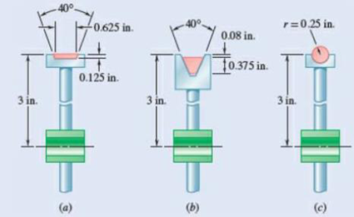
Three different drive belt profiles are to be studied. If at any given time each belt makes contact with one-half of the circumference of its pulley, determine the contact area between the belt and the pulley for each design.
Fig. P5.59
Expert Solution & Answer
Want to see the full answer?
Check out a sample textbook solution
Students have asked these similar questions
Show that a wrench can be replaced with two forces, one of which has a prescribed line of action.
A uniform cable weighing 3 lb/ft is held in the position shown by a horizontal force P applied at B . Knowing that P = 180 lb and 0A= 60°, determine (a) the location of point B, (b) the length of the cable.
2)The forces and couples shown are applied to two screws as a piece of sheet metal is
fastened to a block of wood. Reduce the forces and the couples to an equivalent wrench and
determine (a) the resultant force R, (b) the pitch of the wrench, (c) the point where the axis of
the wrench intersects the xz-plane.
6 lb-in.
6 lb-in.
15 in.
| 11 lb
20 in.
10 lb
В
(A
12
Chapter 5 Solutions
Vector Mechanics for Engineers: Statics, 11th Edition
Ch. 5.1 - 5.1 through 5.9 Locate the centroid of the plane...Ch. 5.1 - 5.1 through 5.9 Locate the centroid of the plane...Ch. 5.1 - 5.1 through 5.9 Locate the centroid of the plane...Ch. 5.1 - Locate the centroid of the plane area shown.Ch. 5.1 - 5.1 through 5.9 Locate the centroid of the plane...Ch. 5.1 - Locate the centroid of the plane area shown.Ch. 5.1 - 5.1 through 5.9 Locate the centroid of the plane...Ch. 5.1 - Locate the centroid of the plane area shown.Ch. 5.1 - Locate the centroid of the plane area shown.Ch. 5.1 - Locate the centroid of the plane area shown.
Ch. 5.1 - 5.10 through 5.15 Locate the centroid of the plane...Ch. 5.1 - Locate the centroid of the plane area shown.Ch. 5.1 - 5.10 through 5.15 Locate the centroid of the plane...Ch. 5.1 - 5.10 through 5.15 Locate the centroid of the plane...Ch. 5.1 - 5.10 through 5.15 Locate the centroid of the plane...Ch. 5.1 - PROBLEM 5.16 Determine the y coordinate of the...Ch. 5.1 - Show that as r1 approaches r2, the location of the...Ch. 5.1 - Prob. 5.18PCh. 5.1 - For the semiannular area of Prob. 5.12, determine...Ch. 5.1 - Prob. 5.20PCh. 5.1 - Prob. 5.21PCh. 5.1 - The horizontal x-axis is drawn through the...Ch. 5.1 - PROBLEM 5.23 The first moment of the shaded area...Ch. 5.1 - Prob. 5.24PCh. 5.1 - Prob. 5.25PCh. 5.1 - Prob. 5.26PCh. 5.1 - A thin, homogeneous wire is bent to form the...Ch. 5.1 - The homogeneous wire ABC is bent into a...Ch. 5.1 - The frame for a sign is fabricated from thin, flat...Ch. 5.1 - The homogeneous wire ABCD is bent as shown and is...Ch. 5.1 - The homogeneous wire ABCD is bent as shown and is...Ch. 5.1 - Determine the distance h for which the centroid of...Ch. 5.1 - Knowing that the distance h has been selected to...Ch. 5.2 - 5.34 through 5.36 Determine by direct integration...Ch. 5.2 - 5.34 through 5.36 Determine by direct integration...Ch. 5.2 - 5.34 through 5.36 Determine by direct integration...Ch. 5.2 - 5.37 through 5.39 Determine by direct integration...Ch. 5.2 - 5.37 through 5.39 Determine by direct integration...Ch. 5.2 - 5.37 through 5.39 Determine by direct integration...Ch. 5.2 - 5.40 and 5.41 Determine by direct integration the...Ch. 5.2 - 5.40 and 5.41 Determine by direct integration the...Ch. 5.2 - Determine by direct integration the centroid of...Ch. 5.2 - 5.43 and 5.44 Determine by direct integration the...Ch. 5.2 - 5.43 and 5.44 Determine by direct integration the...Ch. 5.2 - 5.45 and 5.46 A homogeneous wire is bent into the...Ch. 5.2 - 5.45 and 5.46 A homogeneous wire is bent into the...Ch. 5.2 - A homogeneous wire is bent into the shape shown....Ch. 5.2 - 5.48 and 5.49 Determine by direct integration the...Ch. 5.2 - Prob. 5.49PCh. 5.2 - Determine the centroid of the area shown in terms...Ch. 5.2 - Determine the centroid of the area shown when a =...Ch. 5.2 - Prob. 5.52PCh. 5.2 - 5.53 Determine the volume and the surface area of...Ch. 5.2 - Determine the volume and the surface area of the...Ch. 5.2 - Prob. 5.55PCh. 5.2 - Prob. 5.56PCh. 5.2 - Verify that the expressions for the volumes of the...Ch. 5.2 - Knowing that two equal caps have been removed from...Ch. 5.2 - Three different drive belt profiles are to be...Ch. 5.2 - Determine the capacity, in liters, of the punch...Ch. 5.2 - Determine the volume and total surface area of the...Ch. 5.2 - Determine the volume and weight of the solid brass...Ch. 5.2 - Determine the total surface area of the solid...Ch. 5.2 - Prob. 5.64PCh. 5.2 - The shade for a wall-mounted light is formed from...Ch. 5.3 - 5.66 and 5.67 For the beam and loading shown,...Ch. 5.3 - 5.66 and 5.67 For the beam and loading shown,...Ch. 5.3 - Prob. 5.68PCh. 5.3 - 5.68 through 5.73 Determine the reactions at the...Ch. 5.3 - 5.68 through 5.73 Determine the reactions at the...Ch. 5.3 - 5.68 through 5.73 Determine the reactions at the...Ch. 5.3 - 5.68 through 5.73 Determine the reactions at the...Ch. 5.3 - 5.68 through 5.73 Determine the reactions at the...Ch. 5.3 - Determine (a) the distance a so that the vertical...Ch. 5.3 - Determine (a) the distance a so that the reaction...Ch. 5.3 - Prob. 5.76PCh. 5.3 - Prob. 5.77PCh. 5.3 - The beam AB supports two concentrated loads and...Ch. 5.3 - For the beam and loading of Prob. 5.78, determine...Ch. 5.3 - The cross section of a concrete dam is as shown....Ch. 5.3 - The cross section of a concrete dam is as shown....Ch. 5.3 - The dam for a lake is designed to withstand the...Ch. 5.3 - The base of a dam for a lake is designed to resist...Ch. 5.3 - 5.84 An automatic valve consists of a 9 × 9-in....Ch. 5.3 - Prob. 5.85PCh. 5.3 - The 3 4-m side AB of a tank is hinged at its...Ch. 5.3 - The 3 4-m side of an open tank is hinged at its...Ch. 5.3 - A 0.5 0.8-m gate AB is located at the bottom of a...Ch. 5.3 - A 0.5 0.8-m gate AB is located at the bottom of a...Ch. 5.3 - A 4 2-ft gate is hinged at A and is held in...Ch. 5.3 - Fig. P5.90 5.91 Solve Prob. 5.90 if the gate...Ch. 5.3 - A prismatically shaped gate placed at the end of a...Ch. 5.3 - A prismatically shaped gate placed at the end of a...Ch. 5.3 - A long trough is supported by a continuous hinge...Ch. 5.3 - The square gate AB is held in the position shown...Ch. 5.4 - Consider the composite body shown. Determine (a)...Ch. 5.4 - Prob. 5.97PCh. 5.4 - Prob. 5.98PCh. 5.4 - Prob. 5.99PCh. 5.4 - Prob. 5.100PCh. 5.4 - Prob. 5.101PCh. 5.4 - Prob. 5.102PCh. 5.4 - Prob. 5.103PCh. 5.4 - For the machine element shown, locate the y...Ch. 5.4 - For the machine element shown, locate the x...Ch. 5.4 - 5.106 and 5.107 Locate the center of gravity of...Ch. 5.4 - 5.106 and 5.107 Locate the center of gravity of...Ch. 5.4 - A corner reflector for tracking by radar has two...Ch. 5.4 - A wastebasket, designed to fit in the corner of a...Ch. 5.4 - An elbow for the duct of a ventilating system is...Ch. 5.4 - A window awning is fabricated from sheet metal...Ch. 5.4 - Prob. 5.112PCh. 5.4 - Prob. 5.113PCh. 5.4 - A thin steel wire with a uniform cross section is...Ch. 5.4 - The frame of a greenhouse is constructed from...Ch. 5.4 - Locate the center of gravity of the figure shown,...Ch. 5.4 - Prob. 5.117PCh. 5.4 - A scratch awl has a plastic handle and a steel...Ch. 5.4 - PROBLEM 5.117 A bronze bushing is mounted inside a...Ch. 5.4 - PROBLEM 5.120 A brass collar, of length 2.5 in.,...Ch. 5.4 - PROBLEM 5.121 The three legs of a small...Ch. 5.4 - Prob. 5.122PCh. 5.4 - Determine by direct integration the values of x...Ch. 5.4 - Prob. 5.124PCh. 5.4 - PROBLEM 5.125 Locate the centroid of the volume...Ch. 5.4 - Prob. 5.126PCh. 5.4 - Prob. 5.127PCh. 5.4 - PROBLEM 5.128 Locate the centroid of the volume...Ch. 5.4 - PROBLEM 5.129 Locate the centroid of the volume...Ch. 5.4 - Show that for a regular pyramid of height h and n...Ch. 5.4 - PROBLEM 5.131 Determine by direct integration the...Ch. 5.4 - PROBLEM 5.132 The sides and the base of a punch...Ch. 5.4 - Locate the centroid of the section shown, which...Ch. 5.4 - Locate the centroid of the section shown, which...Ch. 5.4 - Determine by direct integration the location of...Ch. 5.4 - Alter grading a lot, a builder places four stakes...Ch. 5 - 5.137 and 5.138 Locate the centroid of the plane...Ch. 5 - 5.137 and 5.138 Locate the centroid of the plane...Ch. 5 - Prob. 5.139RPCh. 5 - Determine by direct integration the centroid of...Ch. 5 - Determine by direct integration the centroid of...Ch. 5 - The escutcheon (a decorative plate placed on a...Ch. 5 - Determine the reactions at the supports for the...Ch. 5 - A beam is subjected to a linearly distributed...Ch. 5 - A tank is divided into two sections by a 1 1-m...Ch. 5 - Determine the y coordinate of the centroid of the...Ch. 5 - An 8-in.-diameter cylindrical duct and a 4 8-in....Ch. 5 - Three brass plates are brazed to a steel pipe to...
Knowledge Booster


Learn more about
Need a deep-dive on the concept behind this application? Look no further. Learn more about this topic, mechanical-engineering and related others by exploring similar questions and additional content below.Similar questions
- The pipe ABCDE is supported by ball-and-socket joints at A and D and by cable ECF that passes through a ring C with negligible friction and is attached to hooks at E and F. Knowing that the frame supports a uniformly distributed load of 1500 N/m along segment AB, do the following.1) Shows the correct vector representation of the resultant of the two tension forces acting at ring C. Note that T_CF = T_CE = T2) Explain along which line/axis you can sum moments to generate an equilibrium equation with only the magnitude of the tension force as the unknown. Explain your choice.3) Find the magnitude of the tension force.arrow_forwardIn order to unscrew the tapped faucet A , a plumber uses two pipe wrenches as shown. By exerting a 40-lb force on each wrench at a distance of 10 in. from the axis of the pipe and in a direction perpendicular to the pipe and to the wrench, he prevents the pipe from rotating, and thus he avoids loosening or further tightening the joint between the pipe and the tapped elbow C . Determine (a) the angle 0 that the wrench at A should form with the vertical if elbow C is not to rotate about the vertical, (b) the force-couple system at C equivalent to the two 40-lb forces when this condition is satisfied.arrow_forwardGear A weighs 1.4 lb and has a radius of gyration of 1.2 in.; gear B weighs 5.2 lb and has a radius of gyration of 2.8 in.; gear C weighs 10.7 lb and has a radius of gyration of 4.4 in. Knowing a couple M of constant magnitude of 39 lb.in. is applied to gear A, determine the tangential force that gear B exerts on gear C. M A 2 in. 2 in. 4 in. B 6 in.arrow_forward
- Gear A weighs 1.4 lb and has a radius of gyration of 1.2 in.; gear B weighs 5.2 lb and has a radius of gyration of 2.8 in.; gear C weighs 10.7 lb and has a radius of gyration of 4.4 in. Knowing a couple M of constant magnitude of 39 lb.in. is applied to gear A, determine the tangential force that gear B exerts on gear C. M 2 in. 2 in. 4 in. B 6 in. сarrow_forwardMechanics ... determine the moments in a and barrow_forward2. A person's arm is used for ergonomic studies. If the distance of the AB, BC, and CD segments are 35.0 mm, 28.0 mm, and 19.0 mm, respectively, and the model is holding a small 1.5-lb load on the distal metacarpals of her hand . Determine the magnitude and direction of the moment of force with respect to a) to the shoulder joint, b) to the olecranon joint, c) to the carpal joint.arrow_forward
- Determine the value of w and P such that the resultant of the system is a downward force of magnitude 1200 N acting 3.6 m to the right of A. Determine the magnitude of the uniform load w. a.252 N/m b.646.1 N/m c.387.7 N/m d.553.8 N/marrow_forwardIn the assembly shown, sags of s and 1.5 s resulted when the two cylinders were suspended from the rings at A and B, respectively. If s = 0 when the cylinders are removed, determine the following: a. the horizontal distance x (mm) moved by point B/ b. the mass (kg) of the two cylinders , c. the forces (N) in the two springs,. d. the tension (N) in cable AB e. 2 m aterial. The Mate 1 m 2 m Thi our 1.5 m may be subject to copyright i pepertyo do www nt to Part IV: The Law on Copyright 1.5s works that are subject to copyright nd the copyright owners have the c Note: Use 9.81m/s? for the icate y be s. constant and kap=134 N/m. Parameter and ommune s = 0.8 + 0.0003*345 0.9035 m s = 0.8 + 0.0003*XYZ m [2|0|2|1||1| 3|6|2|1 Example Student Number (SN) mwwarrow_forwardThe frictional resistance of a thrust bearing decreases as the shaft and bearing surfaces wear out. It is generally assumed that the wear is directly proportional to the distance traveled by any given point of the shaft and thus to the distance r from the point to the axis of the shaft. Assuming then that the normal force per unit area is inversely proportional to r , show that the magnitude M of the couple required to overcome the frictional resistance of a worn-out end bearing (with contact over the full circular area) is equal to 75 percent of the value given by Eq. (8.9) for a new bearing.arrow_forward
- In order to unscrew the tapped faucet A, a plumber uses two pipe wrenches as shown. By exerting a 40-lb force on each wrench, at a distance of 10 in. from the axis of the pipe and in a direction perpendicular to the pipe and to the wrench, he prevents the pipe from rotating, and thus avoids loosening or further tightening the joint between the pipe and the tapped elbow C. Determine (a) the angle θ that the wrench at A should form with the vertical if elbow C is not to rotate about the vertical, (b) the force-couple system at Cequivalent to the two 40-lb forces when this condition is satisfied.arrow_forwardA rigid rod resting on a fulcrum has the following 20-lb forces acting on it. A is attached 2 feet from the left of the fulcrum acting vertical upward. B is 4 feet to the left of the fulcrum, acting downward at an angle of 30° with respect to the horizontal. C is 6 feet from the left of the fulcrum, acting upward with an angle of 45° with respect to the horizontal. D is attached 2 feet at the right of the fulcrum, acting downward at an angle of 60° respect to the horizontal. Where can a 20 lb force be placed to put the system in equilibrium?PS: FREE BODY DIAGRAM AND SOLUTIONarrow_forwardSolve Prob. 4.91, assuming that the pulley rotates at a constant rate and that TB = 104 N, T'B = 84 N, and TC= 175 N.(Reference to Problem 4.91):Two transmission belts pass over a double-sheaved pulley that is attached to an axle supported by bearings at A and D . The radius of the inner sheave is 125 mm and the radius of the outer sheave is 250 mm. Knowing that when the system is at rest, the tension is 90 N in both portions of belt B and 150 N in both portions of belt C, determine the reactions at A and D . Assume that the bearing at D does not exert any axial thrust.arrow_forward
arrow_back_ios
SEE MORE QUESTIONS
arrow_forward_ios
Recommended textbooks for you
 Elements Of ElectromagneticsMechanical EngineeringISBN:9780190698614Author:Sadiku, Matthew N. O.Publisher:Oxford University Press
 Mechanics of Materials (10th Edition)Mechanical EngineeringISBN:9780134319650Author:Russell C. HibbelerPublisher:PEARSON
 Thermodynamics: An Engineering ApproachMechanical EngineeringISBN:9781259822674Author:Yunus A. Cengel Dr., Michael A. BolesPublisher:McGraw-Hill Education
 Control Systems EngineeringMechanical EngineeringISBN:9781118170519Author:Norman S. NisePublisher:WILEY
 Mechanics of Materials (MindTap Course List)Mechanical EngineeringISBN:9781337093347Author:Barry J. Goodno, James M. GerePublisher:Cengage Learning
 Engineering Mechanics: StaticsMechanical EngineeringISBN:9781118807330Author:James L. Meriam, L. G. Kraige, J. N. BoltonPublisher:WILEY
Elements Of Electromagnetics
Mechanical Engineering
ISBN:9780190698614
Author:Sadiku, Matthew N. O.
Publisher:Oxford University Press
Mechanics of Materials (10th Edition)
Mechanical Engineering
ISBN:9780134319650
Author:Russell C. Hibbeler
Publisher:PEARSON
Thermodynamics: An Engineering Approach
Mechanical Engineering
ISBN:9781259822674
Author:Yunus A. Cengel Dr., Michael A. Boles
Publisher:McGraw-Hill Education
Control Systems Engineering
Mechanical Engineering
ISBN:9781118170519
Author:Norman S. Nise
Publisher:WILEY
Mechanics of Materials (MindTap Course List)
Mechanical Engineering
ISBN:9781337093347
Author:Barry J. Goodno, James M. Gere
Publisher:Cengage Learning
Engineering Mechanics: Statics
Mechanical Engineering
ISBN:9781118807330
Author:James L. Meriam, L. G. Kraige, J. N. Bolton
Publisher:WILEY
Types Of loads - Engineering Mechanics | Abhishek Explained; Author: Prime Course;https://www.youtube.com/watch?v=4JVoL9wb5yM;License: Standard YouTube License, CC-BY