
Electronics Fundamentals: Circuits, Devices & Applications
8th Edition
ISBN: 9780135072950
Author: Thomas L. Floyd, David Buchla
Publisher: Prentice Hall
expand_more
expand_more
format_list_bulleted
Videos
Textbook Question
Chapter 5, Problem 49P
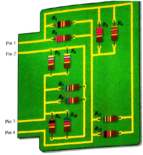
For the circuit board shown in Figure 5-82, determine the resistance between the following pins if there is a short between pins 3 and 4.
- pins 1 and 2
- pins 2 and 3
- pins 2 and 4
- pins 1 and 4
Expert Solution & Answer
Want to see the full answer?
Check out a sample textbook solution
Students have asked these similar questions
An ammeter has a current range of 0-5 A, and its internal resistance is 0.2 N. In
order to change the range to 0-25 A, we need to add a resistance of
(A) 0.8 N in series with the meter
(B) 1.0 N in series with the meter
(C) 0.04 N in parallel with the meter
(D) 0.05 N in parallel with the meter
Find the current I in the figure below using nodal method. All resistors are in ohms.
A voltage divider consists of a 3000 – ohm, a 5000 – ohm, and 10000 – ohm resistor in series and the series current is 15 mA. Find (a) the voltage drop across each resistance and (b) the total voltage.
Chapter 5 Solutions
Electronics Fundamentals: Circuits, Devices & Applications
Ch. 5 - Prob. 1TFQCh. 5 - The total resistance of parallel resistors is...Ch. 5 - The product-over-sum rule works for any number of...Ch. 5 - In a parallel circuit, the voltage is larger on a...Ch. 5 - Prob. 5TFQCh. 5 - Prob. 6TFQCh. 5 - Prob. 7TFQCh. 5 - In the current-divider formula, Ix=(RT/Rx)lT, the...Ch. 5 - Prob. 9TFQCh. 5 - The total power dissipated by parallel resistors...
Ch. 5 - In a parallel circuit, each resistor has the same...Ch. 5 - When a 1.2k resistor and a 100 resistor are...Ch. 5 - Prob. 3STCh. 5 - Eight resistors are in parallel. The two...Ch. 5 - When an additional resistor is connected across an...Ch. 5 - If one of the resistors in a parallel circuit is...Ch. 5 - The currents into a node are along two paths. One...Ch. 5 - Prob. 8STCh. 5 - Prob. 9STCh. 5 - Prob. 10STCh. 5 - In a certain three-branch parallel circuit,...Ch. 5 - Prob. 12STCh. 5 - Prob. 13STCh. 5 - Prob. 14STCh. 5 - Determine the cause for each set of symptoms....Ch. 5 - Prob. 2TSCCh. 5 - Prob. 3TSCCh. 5 - Prob. 4TSCCh. 5 - Determine the cause for each set of symptoms....Ch. 5 - Connect the resistors in Figure 5-57 in parallel...Ch. 5 - Determine whether or not all the resistors in...Ch. 5 - Determine the total resistance between pins 1 and...Ch. 5 - The following resistors are connected in parallel:...Ch. 5 - Find the total resistance between nodes A and B...Ch. 5 - Calculate RT for each circuit in Figure 5-60.Ch. 5 - What is the total resistance of eleven 22k...Ch. 5 - Five 15, ten 100, and two 10 resistors are all...Ch. 5 - Determine the voltage across and the current...Ch. 5 - The source voltage in Figure 5-61 is 100 V. How...Ch. 5 - Prob. 11PCh. 5 - The resistance of a 60 W bulb is approximatey 240....Ch. 5 - What is the current in each resistor for the...Ch. 5 - Four equal-value resistors are connected in...Ch. 5 - The following currents are measured in the same...Ch. 5 - There is a total of 500mA of current into five...Ch. 5 - How much current is through R2 and R3 in Figure...Ch. 5 - A trailer has four running lights that draw 0.5A...Ch. 5 - Assume the trailer in Problem 18 has two brake...Ch. 5 - A 10k resistor and a 15k resistor are in parallel...Ch. 5 - How much branch current should each meter in...Ch. 5 - Prob. 22PCh. 5 - Five parallel resistors each handle 40mW. What is...Ch. 5 - Prob. 24PCh. 5 - Six light bulbs are connected in parallel across...Ch. 5 - If one of the bulbs burns out in Problem 25, how...Ch. 5 - In Figure 5-67, the current and voltage...Ch. 5 - Prob. 28PCh. 5 - Find the open resistor in Figure 5-69.Ch. 5 - From the ohmmeter reading in Figure 5-70, can you...Ch. 5 - In the circuit of Figure 5-71, determine...Ch. 5 - The total resistance of a parallel circuit is 25....Ch. 5 - What is the current through each resistor in...Ch. 5 - A certain parallel circuit consists of only 12W...Ch. 5 - Find the values of the unspecified quantities...Ch. 5 - What is the total resistance between terminal A...Ch. 5 - What value of R2 in Figure 5-75 will cause...Ch. 5 - Determine the total current from the source and...Ch. 5 - The electrical circuit in a room is protected with...Ch. 5 - The total resistance of a parallel circuit is 25....Ch. 5 - Prob. 41PCh. 5 - If the total resistance in Figure 5-78 is 200,...Ch. 5 - Determine the unknown resistances in Figure 5-79.Ch. 5 - There is a total of 250 mA into a parallel circuit...Ch. 5 - Prob. 45PCh. 5 - Develop a test procedure to check the circuit in...Ch. 5 - A certain parallel circuit consists of five 12W...Ch. 5 - For the circuit board shown in Figure 5-82,...Ch. 5 - For the circuit board shown in Figure 5-82,...Ch. 5 - Open file P05-50; files are found at...Ch. 5 - Open file P05-51. Using current measurements,...Ch. 5 - Open file P05-52. Using current measurements,...
Knowledge Booster


Learn more about
Need a deep-dive on the concept behind this application? Look no further. Learn more about this topic, electrical-engineering and related others by exploring similar questions and additional content below.Similar questions
- use the circuit in the following figure. Simplify the circuit across terminals a-b to a single voltage source in series with a single resistor. 1. Determine the source voltage in volts up to 2 decimal places.2. Determine the resistance in ohms up to 2 decimal places.arrow_forwardWhat is the voltage across the 50 Ohm and 5 Ohm resistors? Using the loop hole equation, what is the voltage across the R1? What is R1?arrow_forwardI only need part d, please show the solution clearlyarrow_forward
- the values of R1, R2, and R3, are 92 ohms each the values of R4, R5, and R6 are 81 ohms each what is the circuit’s total resistance in ohms?arrow_forward(d) How will the current through resistors R1 and R2 change when another resistor R3 is connected to the divider circuit in the configuration shown in the figure? R1 R2 R3arrow_forwardCalculate values of asked physical quantities of the circuit: The circuits terminal voltage is 16.7V and then resistors A&B are in parallel. The resistance of resistor A, is 6.2 ohm and for B it's 7.9 ohm. What's the current going through each resistor?arrow_forward
- 5. Two resistors of 6 and 18 ohms are connected in parallel and the combination is connected in series with a 2-ohm resistor. Find the current through each of the first two resistors if the current through the 2-ohm resistors is 1.2 amperes. What is the voltage across each resistor?arrow_forwardTwo resistors are connected in series and have the values 10000 Ω ±5 % and 1000000 Ω ±10%.What is the percent uncertainty for the series total resistance?arrow_forward1. Three series resistors are connected across a voltage source Vs. The voltage drops across each resistor are measured and found to be 4.5 V, 6.4 V, and 13.1 V. What is the value of the voltage source Vs? 2. Four resistors are in series with a 100-V source. The voltage drops across three of the resistors are 10 V, 20 V, and 40 V. If the resistance of the fourth resistor is 300 Ω, what is the current through the circuit? 3. The voltage source in circuit is supplying 100 mA of current. Determine IBA, ,VAD and VBC, if ICD = 50 mA.arrow_forward
- Arrange the seven resistors in one circuit such that: •R1 and R2 are in series with each other and the battery. •R2 is connected to R3, R4, and R5 through separate lines. •R5 and R6 are in series with each other. •R3, R4, and R6 are connected to R7 through separate circuit lines. •R7 is in series with a switch and the battery.arrow_forwardA 90 ampere current flows into two parallel resistors having resistances of 12 and 24 ohms. Determine the current passing through the 24 ohm resistorarrow_forwardwhen would you connect batteries in series compared to connecting batteries in parallelarrow_forward
arrow_back_ios
SEE MORE QUESTIONS
arrow_forward_ios
Recommended textbooks for you
 Delmar's Standard Textbook Of ElectricityElectrical EngineeringISBN:9781337900348Author:Stephen L. HermanPublisher:Cengage Learning
Delmar's Standard Textbook Of Electricity
Electrical Engineering
ISBN:9781337900348
Author:Stephen L. Herman
Publisher:Cengage Learning
Introduction to Two-Port Networks; Author: ALL ABOUT ELECTRONICS;https://www.youtube.com/watch?v=ru2ItcD6unI;License: Standard Youtube License