
Electronics Fundamentals: Circuits, Devices & Applications
8th Edition
ISBN: 9780135072950
Author: Thomas L. Floyd, David Buchla
Publisher: Prentice Hall
expand_more
expand_more
format_list_bulleted
Concept explainers
Videos
Textbook Question
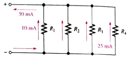
Chapter 5, Problem 17P
How much current is through
Show how to connect ammeters to measure these currents.
Expert Solution & Answer
Want to see the full answer?
Check out a sample textbook solution
Students have asked these similar questions
SECTION 5-6 Kirchhoff's Voltage Law
32. The following voltage drops are measured across three resistors in series: 5.5 V, 8.2 V,
and 12.3 V. What is the value of the source voltage to which these resistors are
connected?
33. Five resistors are in series with a 20 V source. The voltage drops across four of the
resistors are 1.5 V, 5.5 V, 3 V, and 6 V. How much voltage is dropped across the fifth
resistor?
34. Determine the unspecified voltage drop(s) in each circuit of Figure 5-78. Show how to
connect a voltmeter to measure cach unknown voltage drop.
► FIGURE 5-78
2 V
V2
3.2 V
8 V
R
15 VE
2R
0.5 V
1.5 V
4 R
3R
(b)
Given the circuit in Figure 5-8, the voltage drop across R1 is 60 V. The drop across R2 is 45 V. What
is the resistance value of R2?
60 V
300 Q
R1
R2
45 V
Figure 5-8
O 345 2
O 225 Q
O 450 2
O 400 Q
080
w tv
14
Determine the unknown voltage drop, 5, in Figure 5-35.
12 V
FIGURE 5-35
50
6V
15
Chapter 5 Solutions
Electronics Fundamentals: Circuits, Devices & Applications
Ch. 5 - Prob. 1TFQCh. 5 - The total resistance of parallel resistors is...Ch. 5 - The product-over-sum rule works for any number of...Ch. 5 - In a parallel circuit, the voltage is larger on a...Ch. 5 - Prob. 5TFQCh. 5 - Prob. 6TFQCh. 5 - Prob. 7TFQCh. 5 - In the current-divider formula, Ix=(RT/Rx)lT, the...Ch. 5 - Prob. 9TFQCh. 5 - The total power dissipated by parallel resistors...
Ch. 5 - In a parallel circuit, each resistor has the same...Ch. 5 - When a 1.2k resistor and a 100 resistor are...Ch. 5 - Prob. 3STCh. 5 - Eight resistors are in parallel. The two...Ch. 5 - When an additional resistor is connected across an...Ch. 5 - If one of the resistors in a parallel circuit is...Ch. 5 - The currents into a node are along two paths. One...Ch. 5 - Prob. 8STCh. 5 - Prob. 9STCh. 5 - Prob. 10STCh. 5 - In a certain three-branch parallel circuit,...Ch. 5 - Prob. 12STCh. 5 - Prob. 13STCh. 5 - Prob. 14STCh. 5 - Determine the cause for each set of symptoms....Ch. 5 - Prob. 2TSCCh. 5 - Prob. 3TSCCh. 5 - Prob. 4TSCCh. 5 - Determine the cause for each set of symptoms....Ch. 5 - Connect the resistors in Figure 5-57 in parallel...Ch. 5 - Determine whether or not all the resistors in...Ch. 5 - Determine the total resistance between pins 1 and...Ch. 5 - The following resistors are connected in parallel:...Ch. 5 - Find the total resistance between nodes A and B...Ch. 5 - Calculate RT for each circuit in Figure 5-60.Ch. 5 - What is the total resistance of eleven 22k...Ch. 5 - Five 15, ten 100, and two 10 resistors are all...Ch. 5 - Determine the voltage across and the current...Ch. 5 - The source voltage in Figure 5-61 is 100 V. How...Ch. 5 - Prob. 11PCh. 5 - The resistance of a 60 W bulb is approximatey 240....Ch. 5 - What is the current in each resistor for the...Ch. 5 - Four equal-value resistors are connected in...Ch. 5 - The following currents are measured in the same...Ch. 5 - There is a total of 500mA of current into five...Ch. 5 - How much current is through R2 and R3 in Figure...Ch. 5 - A trailer has four running lights that draw 0.5A...Ch. 5 - Assume the trailer in Problem 18 has two brake...Ch. 5 - A 10k resistor and a 15k resistor are in parallel...Ch. 5 - How much branch current should each meter in...Ch. 5 - Prob. 22PCh. 5 - Five parallel resistors each handle 40mW. What is...Ch. 5 - Prob. 24PCh. 5 - Six light bulbs are connected in parallel across...Ch. 5 - If one of the bulbs burns out in Problem 25, how...Ch. 5 - In Figure 5-67, the current and voltage...Ch. 5 - Prob. 28PCh. 5 - Find the open resistor in Figure 5-69.Ch. 5 - From the ohmmeter reading in Figure 5-70, can you...Ch. 5 - In the circuit of Figure 5-71, determine...Ch. 5 - The total resistance of a parallel circuit is 25....Ch. 5 - What is the current through each resistor in...Ch. 5 - A certain parallel circuit consists of only 12W...Ch. 5 - Find the values of the unspecified quantities...Ch. 5 - What is the total resistance between terminal A...Ch. 5 - What value of R2 in Figure 5-75 will cause...Ch. 5 - Determine the total current from the source and...Ch. 5 - The electrical circuit in a room is protected with...Ch. 5 - The total resistance of a parallel circuit is 25....Ch. 5 - Prob. 41PCh. 5 - If the total resistance in Figure 5-78 is 200,...Ch. 5 - Determine the unknown resistances in Figure 5-79.Ch. 5 - There is a total of 250 mA into a parallel circuit...Ch. 5 - Prob. 45PCh. 5 - Develop a test procedure to check the circuit in...Ch. 5 - A certain parallel circuit consists of five 12W...Ch. 5 - For the circuit board shown in Figure 5-82,...Ch. 5 - For the circuit board shown in Figure 5-82,...Ch. 5 - Open file P05-50; files are found at...Ch. 5 - Open file P05-51. Using current measurements,...Ch. 5 - Open file P05-52. Using current measurements,...
Knowledge Booster


Learn more about
Need a deep-dive on the concept behind this application? Look no further. Learn more about this topic, electrical-engineering and related others by exploring similar questions and additional content below.Similar questions
- Determine I1, h, and Ig in Figure 5-38. Vcc -12 V R1 33 kN RC 1.8 kN Ppc = 150 %3D RE R2 5.6 kN 560 2 FIGURE 5-38arrow_forwardWhat is the Norton's resistance as seen from A-B in the circuit shown? All resistances are in ohms. Round off to the nearest tenth digit. 10V HIH Answer:arrow_forwardThe resistors are connected in series across a 120-V source. The first resistor is 50 Q, the current through the second resistor is 0.5 A, and the voltage drop across the third resistor is 50 V. What are the resistances of the first and third resistors ?arrow_forward
- Refer to the circuit shown in Figure 6-22. The circuit has an applied voltage of 24 V and the resistors have values as follows: R1=1kR2=300R3=750R4=1k An ammeter and a voltmeter indicate the following values: IT=42.5mAI1=24mAE1=24VI2=18.5mAE2=5.5VI3=0AE3=18.5VI4=18.5mAE4=18.5V What is the most likely problem with this circuit? FIGURE 8-22 Determine resistor values using the color code and find all missing electrical values.arrow_forwardThe voltage drop of a series circuit is _____. a. the amount of voltage lost through any load b. proportional to the resistance in that part of the circuit c. equal to the voltage being applied to the circuit d. all of the abovearrow_forwardFor the series circuit shown, what is the voltage drop across each resistor?What is the current through each resistor?arrow_forward
- 500 V 0.35 A 0.53 A The total current flowing in the circuit in Figure 5-9 is: 1.06 A 470 92 2.82 A www 470 Ω Figure 5-9 • 470 Ωarrow_forwardIn the following series circuit, find the equivalent resistance and voltage across each resistance. Given the following: R1=8kΩ R2=6kΩ R3=10kΩ VT=225Varrow_forwardto the po Five batteries are connected in parallel to supply a certain load. Each battery consists of 12 cells in series. Each cell has an emf of 2 V and an internal resistance of 0.15 ohm. What should be the resistance of the load so that the total power consumed is 384 W? 130 Y source and the total power taken byarrow_forward
- 5. Two resistors of 6 and 18 ohms are connected in parallel and the combination is connected in series with a 2-ohm resistor. Find the current through each of the first two resistors if the current through the 2-ohm resistors is 1.2 amperes. What is the voltage across each resistor?arrow_forwardFive batteries are connected in parallel to supply a certain load. Each battery consist od 12 cells in series. Each cell has an emf of 2v and the internal resistance of each cell is 0.15ohms. What should be the resistance of the load so that the total power consumed is 384 watts?arrow_forwardThe fact that the sum of the resistor voltage drops equals the applied voltage in a series circuit is the basis forarrow_forward
arrow_back_ios
SEE MORE QUESTIONS
arrow_forward_ios
Recommended textbooks for you
 Electricity for Refrigeration, Heating, and Air C...Mechanical EngineeringISBN:9781337399128Author:Russell E. SmithPublisher:Cengage Learning
 Delmar's Standard Textbook Of ElectricityElectrical EngineeringISBN:9781337900348Author:Stephen L. HermanPublisher:Cengage Learning
Electricity for Refrigeration, Heating, and Air C...
Mechanical Engineering
ISBN:9781337399128
Author:Russell E. Smith
Publisher:Cengage Learning
Delmar's Standard Textbook Of Electricity
Electrical Engineering
ISBN:9781337900348
Author:Stephen L. Herman
Publisher:Cengage Learning
Current Divider Rule; Author: Neso Academy;https://www.youtube.com/watch?v=hRU1mKWUehY;License: Standard YouTube License, CC-BY