
Concept explainers
Videos
A rigid circular plate of 125-mm radius is attached to a solid 150 × 200-mm rectangular post, with the center of the plate directly above the center of the post. If a 4-kN force P is applied at E with θ = 30°, determine (a) the stress at point A, (b) the stress at point B, (c) the point where the neutral axis intersects line ABD.
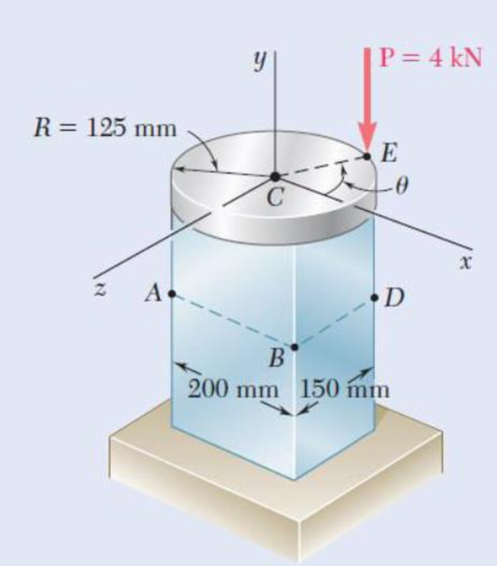
Fig. P4.148
(a)
Find the value of stress at point A.
Answer to Problem 148P
The stress at point A is
Explanation of Solution
Given information:
The radius of the circular plate is
The width of the rectangular post is
The applied force is
Calculation:
Sketch the cross section of disk as shown in Figure 1.
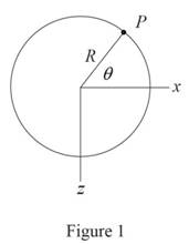
Refer to Figure 1.
Consider the value of angle
Calculate the moment along
Substitute
Calculate the moment along
Substitute
Sketch the cross section of the rectangular post as shown in Figure 2.
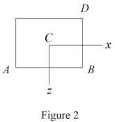
Refer to Figure 2.
Calculate the area
Substitute
Calculate the moment of inertia along
Substitute
Calculate the moment of inertia along
Substitute
Calculate the stress
Refer to Figure 2.
The location of point A along
The location of point A along
Calculate the stress at A
Substitute
Hence, the stress at A is
(b)
The values of stress at B.
Answer to Problem 148P
The stress at B is
Explanation of Solution
Given information:
Calculation:
Calculate the stress at B
Refer to Figure 2 in part (a).
The location of point B along
The location of point B along
Substitute
Hence, the stress at B is
(c)
The point where the neutral axis intersect ABD.
Answer to Problem 148P
The point where the neutral axis intersect ABD is
Explanation of Solution
Given information:
Calculation:
The stress at G
Refer to Figure 2 in part (a).
The location of point G along
The location of point G along
Substitute
Show the distance (d) between the point A and the point G as follows:
Thus, The point where the neutral axis intersect ABD is
Want to see more full solutions like this?
Chapter 4 Solutions
EBK MECHANICS OF MATERIALS


- 2.13 A steel plate, which is 1.5 m by 1.5 m and 30 mm thick, is lifted by four cables attached to its corners that meet at a point that is 2 m above the plate. Determine the required cross-sectional area of the cables if the stress in them is not to exceed 20 MPa. Steel plate Prob. 2.13 Cablesarrow_forwardProblem 2.35 The 5-ft concrete post is reinforced with six steel bars, each with a 7/8-in. diameter. Knowing that E, = 29 x 106 psi and E.= 3.6 x 10⁶ psi, determine the normal stresses in the steel and in the %3D concrete when a 200-kip axial centric force is applied to the post. 5 ft 10 in. 10 in. Flg. P2.35arrow_forwardFig. 2 4. A steel shaft of diameter 50 mm and length 1.2 m (E = 210 GPa and v = 0.3) is loaded with multiple force system. At a point in the shaft, the state of stress relative to the x, y, z coordinate system was found to be: [600 0 T = 0 320 MPa -480 (a) Draw a cube element showing the stress components on each coordinate face (Hint: No vector lines for zero stresses; Warning: A stress element without reference axes will receive zero point). (b) From the given stress tensor, determine the values of (i) octahedral normal stress (Goct) and (ii) octahedral shear stress (toct). (c) From your answer in (b), determine (i) dilatational strain energy Udilat '); and (ii) deviatoric strain energy (Udist). (d) Find the total strain energy at the point.arrow_forward
- PROBLEM 1.3 3 in. 30 kips Two solid cylindrical rods AB and BC are welded together at B and loaded as shown. Determine the magnitude of the force P for which the tensile stress in rod AB is twice the magnitude of the compressive stress in rod BC. 30 kips 40 in PROBLEM 1.4 In Prob. 1.3, knowing that P = 40 kips, determine the average normal stress at the midsection of (a) rod AB, (b) rod BC.arrow_forward5.86 The cast iron inverted T-section supports two concentrated loads of magni- tude P. The working stresses are 48 MPa in tension, 140 MPa in compression, and 30 MPa in shear. (a) Show that the neutral axis of the cross section is located at d = 48.75 mm and that the moment of inertia of the cross-sectional area about this axis is I = 11.918 x 106 mm“. (b) Find the maximum allowable value of P. 1.0 m 1.0 m 15 mm 3 m 150 mm NA- d 15 mm 150 mm FIG. P5.86arrow_forwardThe four forces shown are applied to a rigid plate supported by a solid steel post of radius a. Knowing that P= 24 kips and a= 1.6 in., determine the maximum stress in the post when (a) the force at D is removed, (b) the forces at C and D are removedarrow_forward
- A fabric used in air-inflated structures is subjected to a biaxial loading that results in normal stresses ox = 18 ksi and oz = 24 ksi.Knowing that the properties of the fabric can be approximated as E = 12.6 x 10 psi and v = 0.34, determine the change in length of (a) side AB, (b) side BC, (c) diagonal AC.arrow_forward4.17. Determine the components of stress from the results obtained in (a) v=rsin 0, ve = 2r cos 0 (b) VT = cos 0, 1/4 = 0 (c) v = V₁ = 0 (d) v = (1 - 4) cos 0, Ve= - - (1 + 4/4) sin 0 - Barrow_forward+3 in- B in. A vertical force P of magnitude 20 kips is applied at point C located on the axis of symmetry of the cross section of a short column. Knowing that y = 5 in., determine (a) the stress at point A, (b) the stress at point B, (c) the location of the neutral axis. 2 in. 4 in. A 2 in. 2 in. 1 in. (a) (b)arrow_forward
- Two gage marks are placed exactly 250 mm apart on a 12-mm-diameter aluminum rod with E = 73 GPa and an ultimate strength of 140 MPa. Knowing that the distance between the gage marks is 250.28 mm after a load is applied, determine the stress in the rodarrow_forwardPROBLEM 1.2 Two solid cylindrical rods AB and BC are welded together at B and loaded as shown. Knowing that d = 50 mm and dz = 30 mm, find the average normal stress at the midsection of (a) rod AB, (b) rod BC. 300 mm 40 kN 250 mm V30 KNarrow_forwardChapter 4 : Stresses & Strains in Statically Indeterminate Structures I 53 EXERCISE 4.1 1. An alloy bar 800 mm long and 200 mm in cross-section is held between two rigid plates and is subjected to an axial load of 200 kN as shown in Fig. 4.7. | A В C 200 kN 300 500 Fig. 4.7 Find the reactions at the two ends A and C as well as extension of the portion AB. [Ans. 125 kN ; 75 kN ; 0.094 mm] 2. A bar ABC fixed at both ends A and Cis loaded by an axial load (P) at C. If the distances AB and BC are equal to a and b respectively then find the reactions at the ends A and C. 3. An axial force of 20 kN is applied to a steel bar ABC which is fixed at both ends A and C as shown in Fig. 4.8. 2 A = 200 mm A = 100 mm 20 kN+ A В 2 m 1 m Fig. 4.8 Determine the reactions at both the supports and stresses developed in two parts of the bar. Take E = 200 GPa. [Ans. R = R = 10 kN; oAR = 50 MPa (C); oBC = 100 MPa (7)] %3D %3! %3D 4. A prismatic bar ABCD has built-in ends A and D. It is subjected to two point…arrow_forward
 Elements Of ElectromagneticsMechanical EngineeringISBN:9780190698614Author:Sadiku, Matthew N. O.Publisher:Oxford University Press
 Mechanics of Materials (10th Edition)Mechanical EngineeringISBN:9780134319650Author:Russell C. HibbelerPublisher:PEARSON
 Thermodynamics: An Engineering ApproachMechanical EngineeringISBN:9781259822674Author:Yunus A. Cengel Dr., Michael A. BolesPublisher:McGraw-Hill Education
 Control Systems EngineeringMechanical EngineeringISBN:9781118170519Author:Norman S. NisePublisher:WILEY
 Mechanics of Materials (MindTap Course List)Mechanical EngineeringISBN:9781337093347Author:Barry J. Goodno, James M. GerePublisher:Cengage Learning
 Engineering Mechanics: StaticsMechanical EngineeringISBN:9781118807330Author:James L. Meriam, L. G. Kraige, J. N. BoltonPublisher:WILEY