
Concept explainers
Videos
For the curved bar shown, determine the stress at point A when (a) h = 50 mm, (b) h = 60 mm.
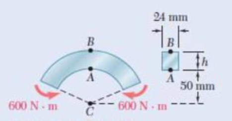
Fig. P4.161 and P4.162
(a)
The stress at point A.
Answer to Problem 161P
The stress at A is
Explanation of Solution
Given information:
The value of h is
The inner
The width and depth of the bar are
The moment (M) is
Calculation:
Calculate the cross-section area (A) of the bar as follows:
Calculate the radius (R) of the neutral surface using the relation:
Substitute
Calculate the mean radius
Substitute
The distance (e) between the neutral axis and the centroid of the cross-section using the relation:
Substitute
Calculate the value of
The distance
Calculate the stress at point A using the relation:
Substitute
Thus, the stress at point A is
(b)
The stress at point A.
Answer to Problem 161P
The stress at A is
Explanation of Solution
Given information:
The value of h is
The inner
The width and depth of the bar are
The moment (M) is
Calculation:
Calculate the cross-section area (A) of the bar as follows:
Calculate the radius (R) of the neutral surface using the relation:
Substitute
Calculate the mean radius
Substitute
The distance (e) between the neutral axis and the centroid of the cross-section using the relation:
Substitute
Calculate the value of
The distance
Calculate the stress at point A using the relation:
Substitute
Thus, the stress at point A is
Want to see more full solutions like this?
Chapter 4 Solutions
EBK MECHANICS OF MATERIALS


- Prob.4: [2.37] The 1.5 m concrete post is reinforced with six steel bars, each with 28 mm diameter. Knowing the E, = 200 GPa and Ec = 200 GPa, determine the normal stresses in the steel and concrete when a 1550 kN axial centric force P is applied to the post. 450 mm 1.5 marrow_forwardPROBLEM 1.3 3 in. 30 kips Two solid cylindrical rods AB and BC are welded together at B and loaded as shown. Determine the magnitude of the force P for which the tensile stress in rod AB is twice the magnitude of the compressive stress in rod BC. 30 kips 40 in PROBLEM 1.4 In Prob. 1.3, knowing that P = 40 kips, determine the average normal stress at the midsection of (a) rod AB, (b) rod BC.arrow_forwardKnowing that the clamp shown has been tightened until P= 400 N, determine (a) the stress at point A, (b) the stress at point B, (c) the location of the neutral axis of section a-a.arrow_forward
- A cast-iron machine part is acted upon by the 3 kN-m couple shown. Know-ing that E= 165 GPa and neglecting the effect of fillets, determine (a) the maximum tensile and compressive stresses in the casting and (b) the radius of curvature of the castingarrow_forwardThe four forces shown are applied to a rigid plate supported by a solid steel post of radius a. Knowing that P= 24 kips and a= 1.6 in., determine the maximum stress in the post when (a) the force at D is removed, (b) the forces at C and D are removedarrow_forward4.19 and 4.20 Knowing that for the extruded beam shown the allowable stress is 120 MPa in tension and 150 MPa in compres- sion, determine the largest couple M that can be applied. 80 mm- 125 mm 54 mm 50 mm 125 mm 40 mm M Fig. P4.20 150 mm Fig. P4.19 Marrow_forward
- 5.86 The cast iron inverted T-section supports two concentrated loads of magni- tude P. The working stresses are 48 MPa in tension, 140 MPa in compression, and 30 MPa in shear. (a) Show that the neutral axis of the cross section is located at d = 48.75 mm and that the moment of inertia of the cross-sectional area about this axis is I = 11.918 x 106 mm“. (b) Find the maximum allowable value of P. 1.0 m 1.0 m 15 mm 3 m 150 mm NA- d 15 mm 150 mm FIG. P5.86arrow_forwardPROBLEM 1.2 Two solid cylindrical rods AB and BC are welded together at B and loaded as shown. Knowing that d = 50 mm and dz = 30 mm, find the average normal stress at the midsection of (a) rod AB, (b) rod BC. 300 mm 40 kN 250 mm V30 KNarrow_forward2.36 A 250-mm bar of 150 x 30-mm rectangular cross section consists of two aluminum layers, 5 mm thick, brazed to a center brass layer of the same thickness. If it is subjected to centric forces of magni- tude P = 30 kN, and knowing that E, = 70 GPa and E, = 105 GPa, determine the normal stress (a) in the aluminum layers, (b) in the brass layer. P' 250 mm 5 mm 5 mm 5 mm Aluminum Brass Aluminum P 30 mm Fig. P2.36arrow_forward
- 4.17. Determine the components of stress from the results obtained in (a) v=rsin 0, ve = 2r cos 0 (b) VT = cos 0, 1/4 = 0 (c) v = V₁ = 0 (d) v = (1 - 4) cos 0, Ve= - - (1 + 4/4) sin 0 - Barrow_forward2.13 A steel plate, which is 1.5 m by 1.5 m and 30 mm thick, is lifted by four cables attached to its corners that meet at a point that is 2 m above the plate. Determine the required cross-sectional area of the cables if the stress in them is not to exceed 20 MPa. Steel plate Prob. 2.13 Cablesarrow_forward2.4 An 18-m-long steel wire of 5-mm diameter is to be used in the manufacture of a prestressed concrete beam. It is observed that the wire stretches 45 mm when a tensile force P is applied. Know- ing that E = 200 GPa, determine (a) the magnitude of the force P, (b) the corresponding normal stress in the wire.arrow_forward
 Elements Of ElectromagneticsMechanical EngineeringISBN:9780190698614Author:Sadiku, Matthew N. O.Publisher:Oxford University Press
 Mechanics of Materials (10th Edition)Mechanical EngineeringISBN:9780134319650Author:Russell C. HibbelerPublisher:PEARSON
 Thermodynamics: An Engineering ApproachMechanical EngineeringISBN:9781259822674Author:Yunus A. Cengel Dr., Michael A. BolesPublisher:McGraw-Hill Education
 Control Systems EngineeringMechanical EngineeringISBN:9781118170519Author:Norman S. NisePublisher:WILEY
 Mechanics of Materials (MindTap Course List)Mechanical EngineeringISBN:9781337093347Author:Barry J. Goodno, James M. GerePublisher:Cengage Learning
 Engineering Mechanics: StaticsMechanical EngineeringISBN:9781118807330Author:James L. Meriam, L. G. Kraige, J. N. BoltonPublisher:WILEY