
Concept explainers
Videos
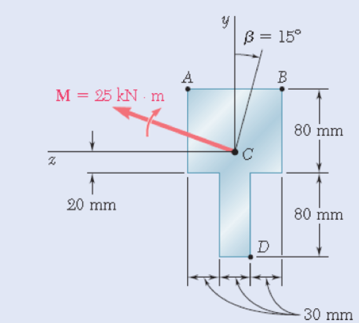
4.127 through 4.134 The couple M is applied to a beam of the cross section shown in a plane forming an angle β with the vertical. Determine the stress at (a) point A, (b) point B, (c) point D.
Flg. P4.129
(a)
Find the stress at point A.
Answer to Problem 129P
The stress at point A is
Explanation of Solution
Given information:
The couple acts in a vertical plane
The angle is
Calculation:
Sketch the beam cross section as shown in Figure 1.
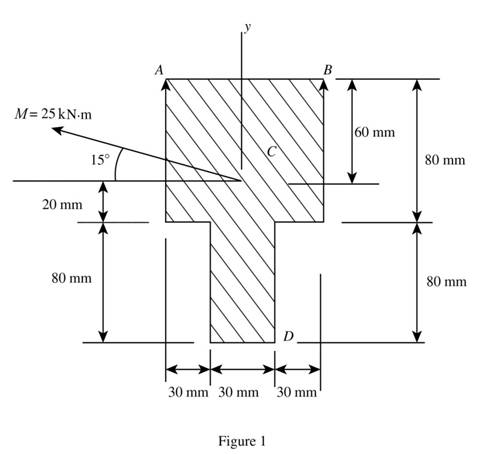
Refer to Figure 1.
Calculate the moment along
Substitute
Calculate the moment along
Substitute
Calculate the moment of inertia along y axis
Calculate the moment of inertia along z axis
Calculate the stress
The location of point A along z axis
The location of point A along y axis
Calculate the stress at point A
Substitute
Therefore, the stress at point A is
(b)
The stress at point B.
Answer to Problem 129P
The stress at point B is
Explanation of Solution
Given information:
The couple acts in a vertical plane
The angle is
Calculation:
Refer to part (a).
The moment along y axis
The moment along z axis
The moment of inertia along y axis
The moment of inertia along z axis
Refer to Figure 1 in part (a).
The location of point B along z axis
The location of point B along y axis
Calculate the stress at point B
Substitute
Therefore, the stress at point B is
(c)
The stress at point D.
Answer to Problem 129P
The stress at point D is
Explanation of Solution
Given information:
The couple acts in a vertical plane
The angle is
Calculation:
Refer to part (a).
The moment along y axis is
The moment along z axis is
The moment of inertia along y axis is
The moment of inertia along z axis is
Refer to Figure 1 in part (a).
The location of point D along z axis
The location of point D along y axis
Calculate the stress at point D
Substitute
Therefore, the stress at point D is
Want to see more full solutions like this?
Chapter 4 Solutions
Mechanics of Materials, 7th Edition


- Knowing that the maximum allowable stress is 41 MPa, determine the magnitude of the largest moment M that can be applied to the component shown. The magnitude of the largest moment M that can be applied to the component is kN·m.arrow_forwardA rod must not stretch more than 6 mm when the tension in the wire is 8 kN. Knowing that E = 105 GPa and that the maximum allowable normal stress is 150 MPa, determine the smallest diameter (mm) rod that should be used.arrow_forwardThe couple M is applied to a beam of the cross section shown in a plane forming an angle β with the vertical. Determine the stress at (a) point A, (b) point B, (c) point D.arrow_forward
- The couple M acts in a vertical plane and is applied to a beam oriented as shown. Determine (a) the angle that the neutral axis forms with the horizontal plane, (b) the maximum tensile stress in the beamarrow_forwardA timber beam AB of length L and rectangular cross section carries a single concentrated load P at its midpoint C. (a) Show that the ratio Tm/ m of the maximum values of the shearing and normal stresses in the beam is equal to h/2L, where h and L are, respectively, the depth and the length of the beam. (b) Determine the depth h and the width b of the beam, knowing that L = 2 m, P = 40 kN, 7m = 960 kPa, and om = 12 MPa.arrow_forwardTo determine the state of stress in a solid rod using the principle of superposition. A solid rod has a diameter of e� = 55 mmmm and is subjected to the loading shown. Let a� = 200 mmmm , b� = 220 mmmm , c� = 350 mmmm , d� = 250 mmmm , and P� = 3.0 kNkN . Take point A to be at the top of the circular cross-section. As shown (Figure 2), a cut was made at A to determine the resultant internal loadings. Determine the moment about the x axis, Mx��. b) Part B - Moment about the z axis at A Part C - Stress due to the normal force To find the state of stress at A, the principle of superposition must be used. If the rod has a diameter of 55 mm , find the stress σA�� due to the normal force. Part D - Stress due to the bending moment about the x axis To find the state of stress at A, the principle of superposition must be used. If the rod has a diameter of 55 mm , find the stress σA�� due to the bending moment about the x axis.arrow_forward
- A 1600-lb-in. couple is applied to a wooden beam, of rectangular cross section 1.5 by 3.5 in., in a plane forming an angle of 308 with the vertical (Fig. ). Determine (a) the maximum stress in the beam and (b) the angle that the neutral surface forms with the horizontal planearrow_forwardThe four forces shown are applied to a rigid plate supported by a solid steel post of radius a. Knowing that P= 24 kips and a= 1.6 in., determine the maximum stress in the post when (a) the force at D is removed, (b) the forces at C and D are removedarrow_forwardThe aluminum rod AD is fitted with a jacketthat is used to apply a hydrostatic pressure of5000 psi to the 12-in. portion BC of the rod.Knowing that E = 10.1 × 10⁶ psi and v = 0.36,determine the forces that should be appliedto the ends A and D of the rod if the axialstrain in portion BC of the rod is to remainzero as the hydrostatic pressure is applied.Determine the forces that should be appliedto the ends A and D if the total length AD ofthe rod is to remain unchanged.arrow_forward
- The structure shown consists of a single member ABCDE with a pin support at A and a roller support at E. Points B and D are at the midpoints of their respective segments. Determine the internal moment acting on I which are located immediately to the left of C. Take N = 5 kN, O = 4 kN, and P = 3 kN.arrow_forwardTwo solid cylindrical rods AB and BC are welded together at B and loaded as shown. Knowing that d1 = 50 mm and d2 = 30 mm, find the average normal stress at the midsection of (a) rod AB, (b) rod BC.arrow_forwardTwo cylindrical rods, one of steel and the other of brass, are joined at C and restrained by rigid supports at A and E. The steel rod has a length of 300 mm while the brass rod has a length of 200 mm. The diameters of the rods are shown in the figure below. A force of 60 kN is applied at point B of the steel segment. For the loading shown and knowing that modulus of elasticity values for steel and brass are respectively Es = 200 GPa and Eb = 105 GPa, determine a.) The reactions at A and E: RA and RE. b.) The deflection of point C from its original location. how to doarrow_forward
 Elements Of ElectromagneticsMechanical EngineeringISBN:9780190698614Author:Sadiku, Matthew N. O.Publisher:Oxford University Press
 Mechanics of Materials (10th Edition)Mechanical EngineeringISBN:9780134319650Author:Russell C. HibbelerPublisher:PEARSON
 Thermodynamics: An Engineering ApproachMechanical EngineeringISBN:9781259822674Author:Yunus A. Cengel Dr., Michael A. BolesPublisher:McGraw-Hill Education
 Control Systems EngineeringMechanical EngineeringISBN:9781118170519Author:Norman S. NisePublisher:WILEY
 Mechanics of Materials (MindTap Course List)Mechanical EngineeringISBN:9781337093347Author:Barry J. Goodno, James M. GerePublisher:Cengage Learning
 Engineering Mechanics: StaticsMechanical EngineeringISBN:9781118807330Author:James L. Meriam, L. G. Kraige, J. N. BoltonPublisher:WILEY