
Concept explainers
Videos
Consider the bridge circuit of Fig. 4.148. Is the bridge balanced? If the 10-kΩ resistor is replaced by an 18-kΩ resistor, what resistor connected between terminals a-b absorbs the maximum power? What is this power?
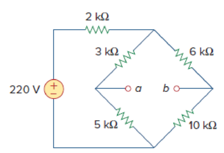
Figure 4.148
Find whether the bridge circuit of Figure 4.148 is balanced. Also find the value of the load resistor connected between the terminals a-b of the circuit and the maximum power absorbed by the load resistor.
Answer to Problem 92P
The bridge circuit is balanced when
Explanation of Solution
Given data:
Refer to Figure 4.148 in the textbook.
The voltage source is
Calculation:
For a bridge to be balanced, the voltage measured at terminals a-b should be zero.
The given circuit is modified as shown in Figure 1.
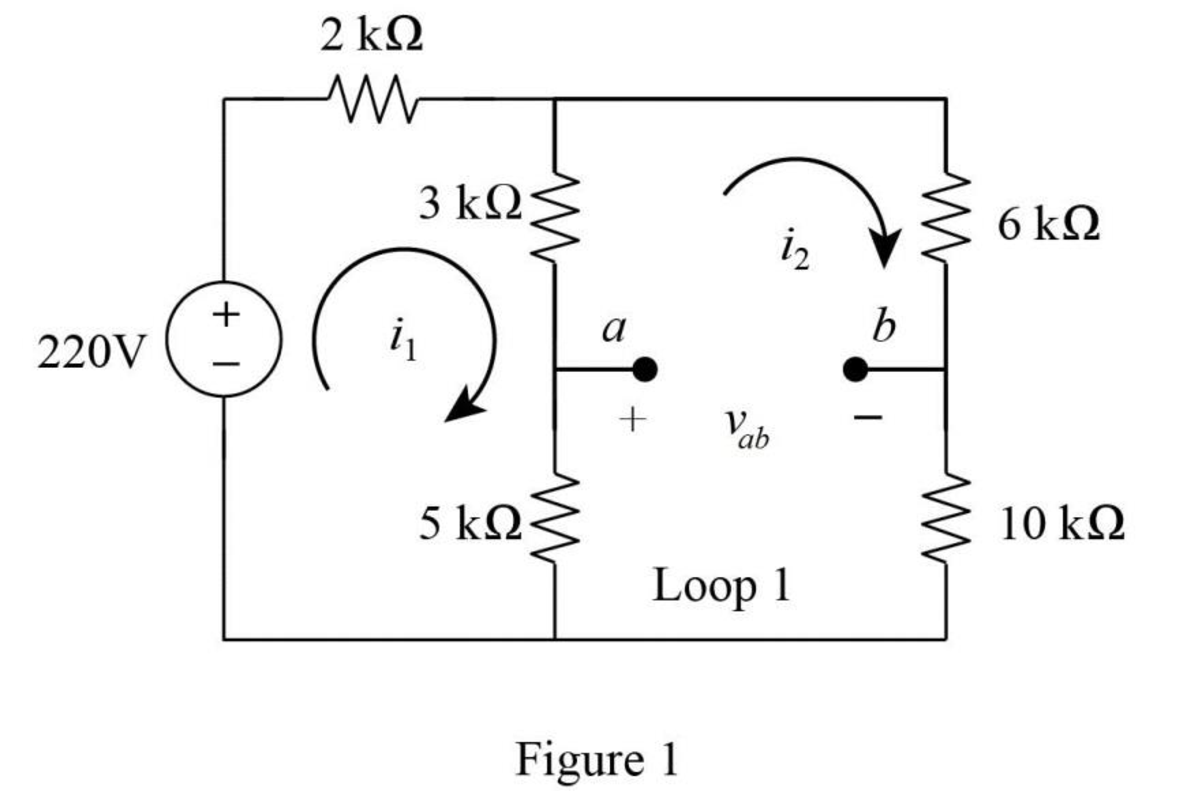
In Figure 1, apply Kirchhoff’s voltage law at loop
In Figure 1, apply Kirchhoff’s voltage law at loop
Substitute equation (2) in equation (1) as follows,
Simplify the equation as follows,
Substitute
In Figure 1, apply Kirchhoff’s voltage law at loop 1 as follows.
Substitute
As the voltage
In Figure 1, when the
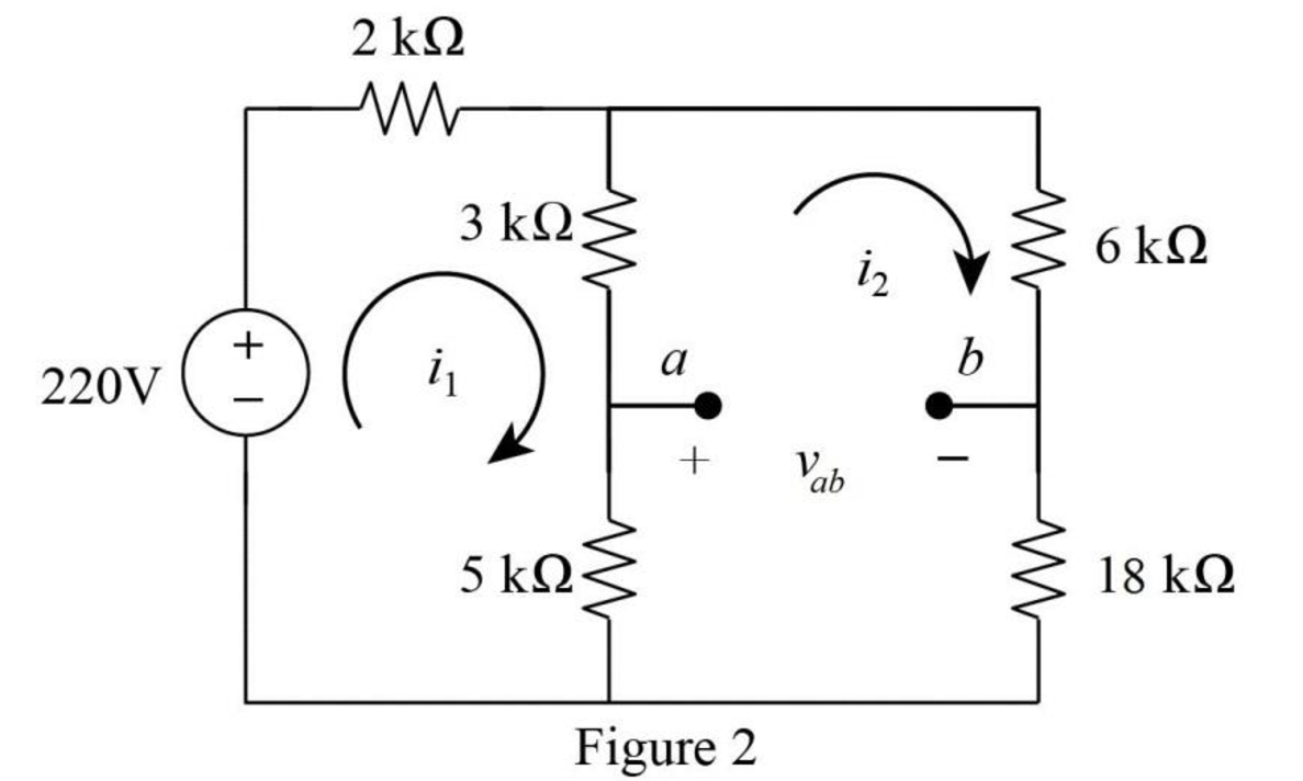
In Figure 2, apply Kirchhoff’s voltage law at loop
In Figure 2, apply Kirchhoff’s voltage law at loop
Substitute
Simplify the equation as follows,
Substitute
In Figure 2, the voltage
Substitute
Since the voltage
Refer to Figure (2).
In Figure (2), find the Thevenin resistance by turning off the
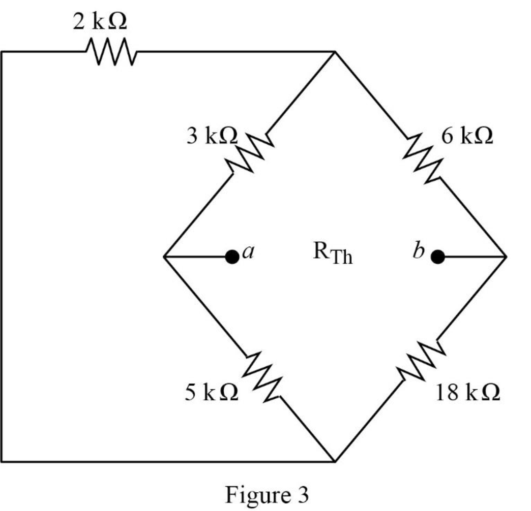
In Figure 3,
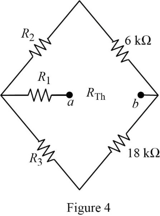
For the wye connection in Figure 4, the value of the resistor
For the wye connection in Figure 4, the value of the resistor
For the wye connection in Figure 4, the value of the resistor
Figure 4 is modified as shown in Figure 5.
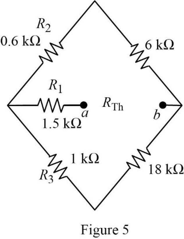
In Figure 5, the Thevenin resistance is,
Simplify the equation as follows,
For maximum power transfer,
The maximum power absorbed by the load resistor is,
Substitute
Conclusion:
Thus, the bridge circuit is balanced when
Want to see more full solutions like this?
Chapter 4 Solutions
EBK FUNDAMENTALS OF ELECTRIC CIRCUITS


- Find the Norton equivalent between terminals 4 and 0. Find the current for the 80 Ohm resistor (RL).arrow_forwardFind voltage across each of the 5 resistors. Find current through each of the 5 resistors. Find power through each of the 5 resistors. My attempt at the solution: I know that total voltage is 24V. I add 12+3+2 since they're in series which equals 17ohms, which reduces total number of resistors. Then I add the parallels: 1/17+1/33=50/561>>>561/50=11.2ohms, then I add remaining 5ohm resistor. 5+11.2=16.2ohms, which is total resistance. Total current would be 24/16.2=1.5A Next I try to solve the following: Voltage across 5ohm resistor: 1.5*5=7.5V, which I know is correct. Voltage across 33ohm: 11.2*1.5=16.8V, which I know is correct. Voltage across 12, 3, and 2: I thought I was correct to do 11.2*1.5=16.8V (since 33 and 17 resistors both equal 11.2ohms), but according to my textbook, that answer is wrong and affects the results for power as well. Current through 5: 7.5/5=1.5A, which is correct. Current through 33: 16.8/33=0.51A, which is correct. Current through 12, 3, and 2:…arrow_forwardQ2/ find Rab in the figure 4 a o 10 2 20 2 10 Ω 30 Ω ww 10 Ω 20 Ω bo wwarrow_forward
- 5. The maximum load current that can be drawn is 15 ka V, = 9 V, R,= 0 A 30 V RL a) 1.4 mA b) 2.3 mA c) 1.8 mA d) 2.5 mAarrow_forwardDesign a Wheatstone bridge circuit that satisfies the given conditions. Include all resistor values and all voltage values. Vi= 30020 mV, Va = 3002 mV, Vo = - 3200 Varrow_forwardIn order to measure a temperature of 25 degrees a thermoresitor type Pt100 is connected in one of the legs of a Wheatstone bridge. The other 3 resistors in the bridge circuit are 100 Ω each. During the measurement the bridge will be: - Unbalanced - Balanced - the balance is not important - the Wheatstone bridge cannot be used in that casearrow_forward
- Electrical devices are not allowed to be connected in series because None of them Power loss is more. O Devices have their different current ratings. Series circuit is complicated. 3 resistors are connected as a form of triangle.lf the resistance of each of them is 5Q, The resistance between any two corners is * O (3/10) Q O (10/3) Q O (5/3) Q (3/5)0arrow_forwardQ2/ find Rab in the figure 4 a 10 Ω 20 Ω 10 Ω 30 2 10 Ω 20 Ω wwarrow_forward4. Find the equivalent resistance of the network between terminals A and B. All resistance values are in ohms. [62] 40 BO- 3 ∞ 2 un wwarrow_forward
- Solve Vx using Superposition. What is the aim of this circuit? * . 2Ω 6 A 4 A Vx 4ix O Vx = Vx1 + Vx2 O ix = ix1 + ix2 ) Vx = Vx1 + Vx2 + Vx3 ) ix = ix1 + ix2 + ix3 +arrow_forwardVS = 15V , IA = 6mA, R1 = 3KΩ, R2 = 6KΩ, and R3 = 18KΩ Using Thevenin or Norton circuit determine the voltage drop V4 in R4 if R4 = 3KΩ and determine the maximum power transfer in R4.arrow_forwardIn the circuit of Fig. 4_5, which of the following statements is true? 2 V Oi3= 0.157 A Oi₁=-2 A 1₂=3 A 13=2A ΤΩ www 50 Fig. 4_5 9Ω 3 V E '6Ω 70arrow_forward
 Introductory Circuit Analysis (13th Edition)Electrical EngineeringISBN:9780133923605Author:Robert L. BoylestadPublisher:PEARSON
 Delmar's Standard Textbook Of ElectricityElectrical EngineeringISBN:9781337900348Author:Stephen L. HermanPublisher:Cengage Learning
 Programmable Logic ControllersElectrical EngineeringISBN:9780073373843Author:Frank D. PetruzellaPublisher:McGraw-Hill Education
 Fundamentals of Electric CircuitsElectrical EngineeringISBN:9780078028229Author:Charles K Alexander, Matthew SadikuPublisher:McGraw-Hill Education
 Electric Circuits. (11th Edition)Electrical EngineeringISBN:9780134746968Author:James W. Nilsson, Susan RiedelPublisher:PEARSON
 Engineering ElectromagneticsElectrical EngineeringISBN:9780078028151Author:Hayt, William H. (william Hart), Jr, BUCK, John A.Publisher:Mcgraw-hill Education,