
Concept explainers
Videos
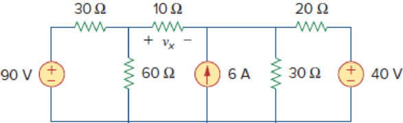
Use superposition to obtain vx in the circuit of Fig. 4.85. Check your result using PSpice or MultiSim.
Figure 4.85
Find the value of the voltage
Answer to Problem 17P
The value of the voltage
Explanation of Solution
Given data:
Refer to Figure 4.85 in the textbook.
Calculation:
In the given circuit, since there are three sources, let
Where
When
The given circuit is modified as shown in Figure 1.
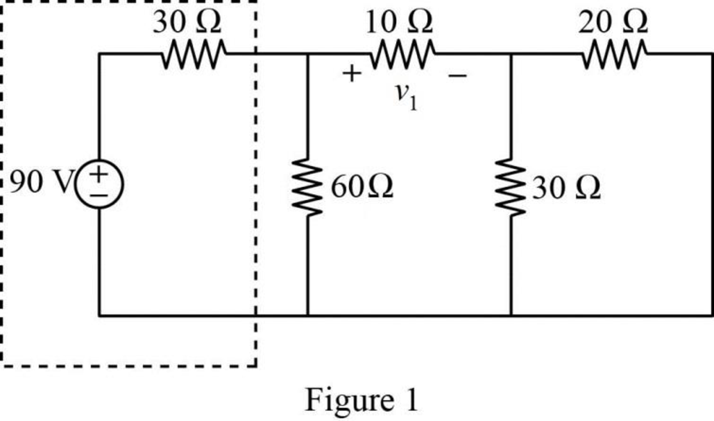
In Figure 1, the voltage source with series resistance is converted into current source with parallel resistance by source transformation method.
That is,
The source transformation is shown in Figure 2.
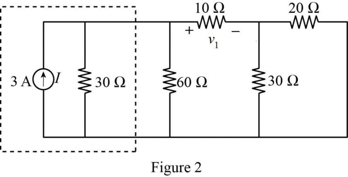
In Figure 2,
Similarly,
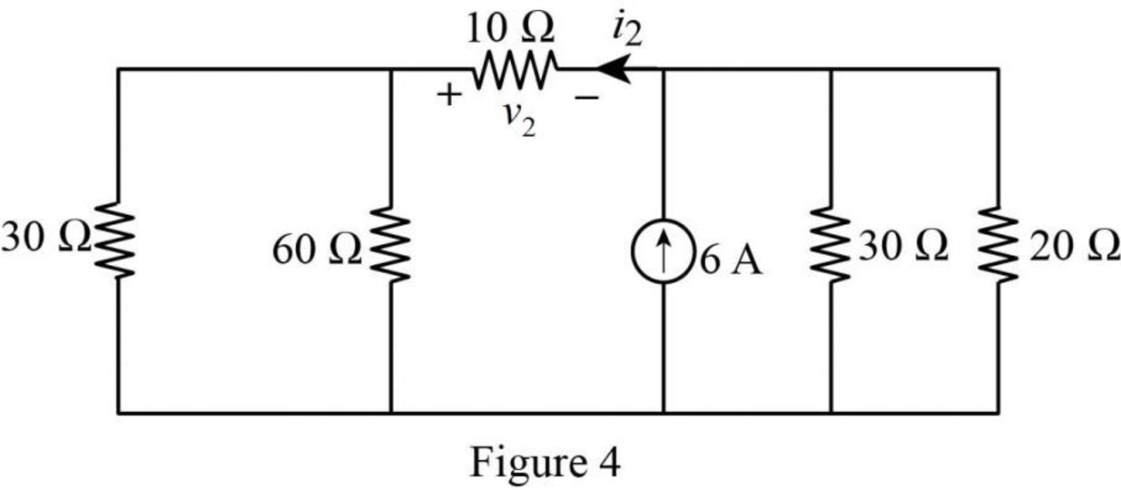
The modified Figure is shown in Figure 3.
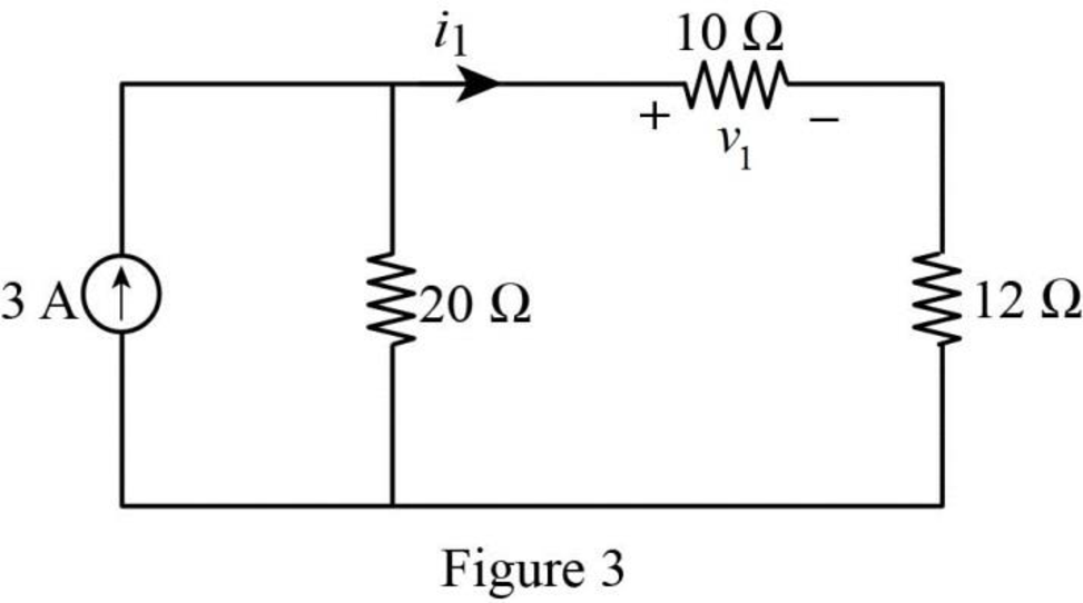
In Figure 3, the current
The voltage
Substitute
When
The given circuit is modified as shown in Figure 4.
In Figure 4,
Similarly,
The modified Figure is shown in Figure 5.
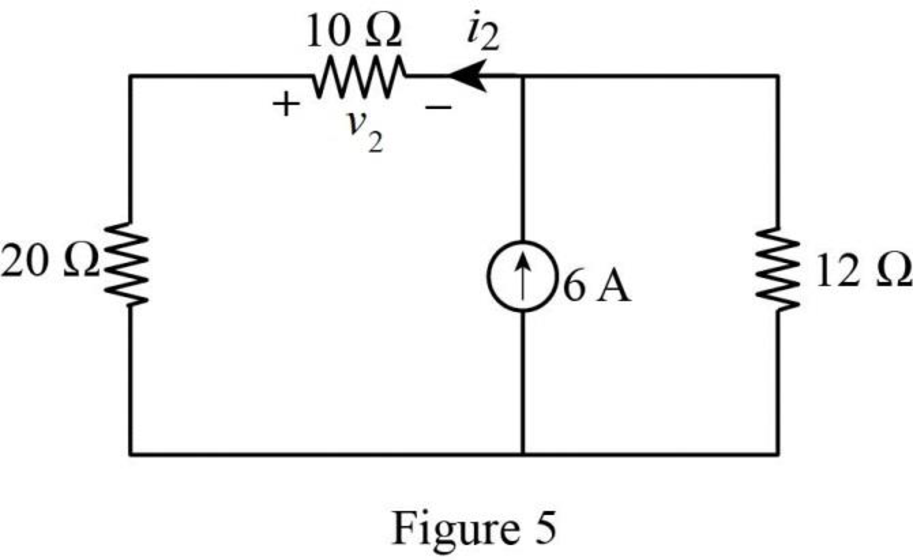
In Figure 5, the current
The voltage
Substitute
When
The given circuit is modified as shown in Figure 6.
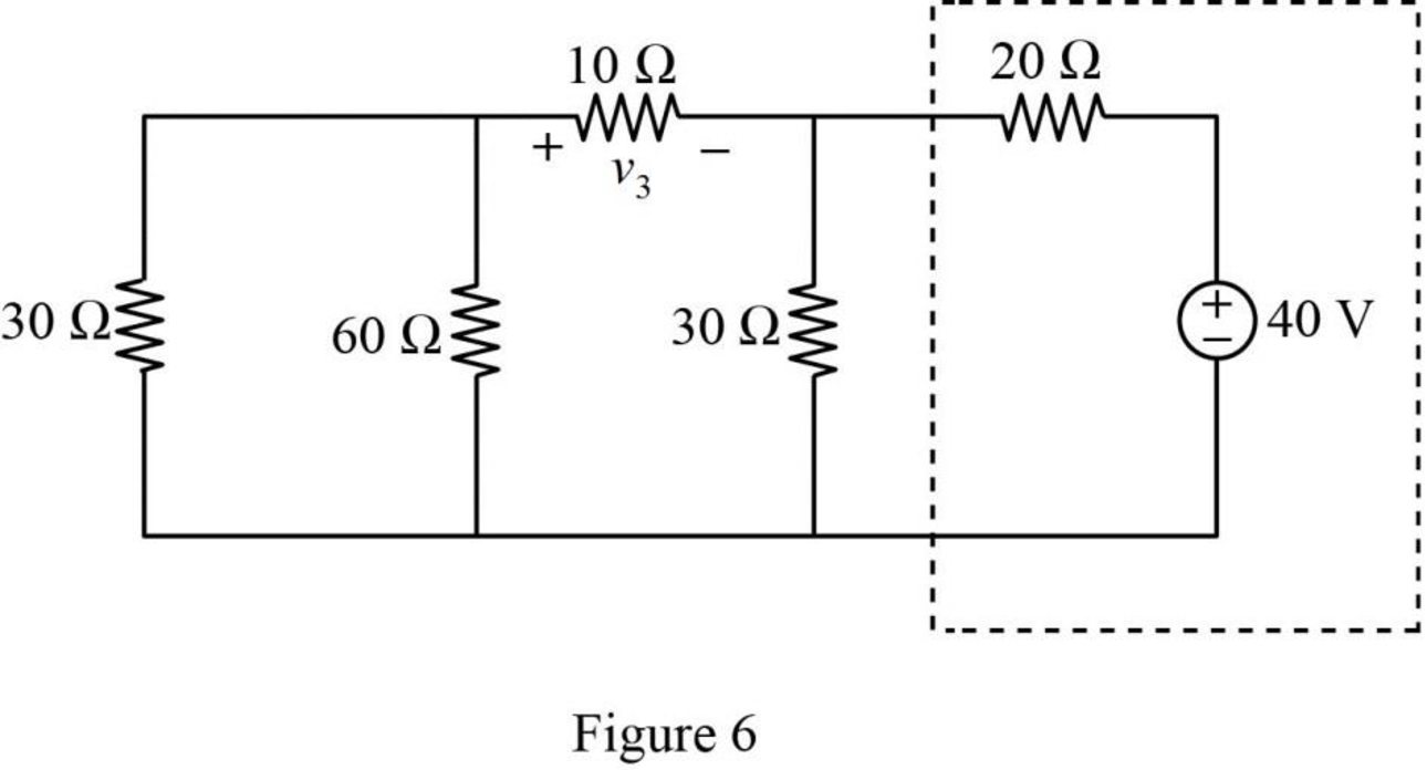
In Figure 6, the voltage source with series resistance is converted into current source with parallel resistance by source transformation method.
That is,
The source transformation is shown in Figure 7.
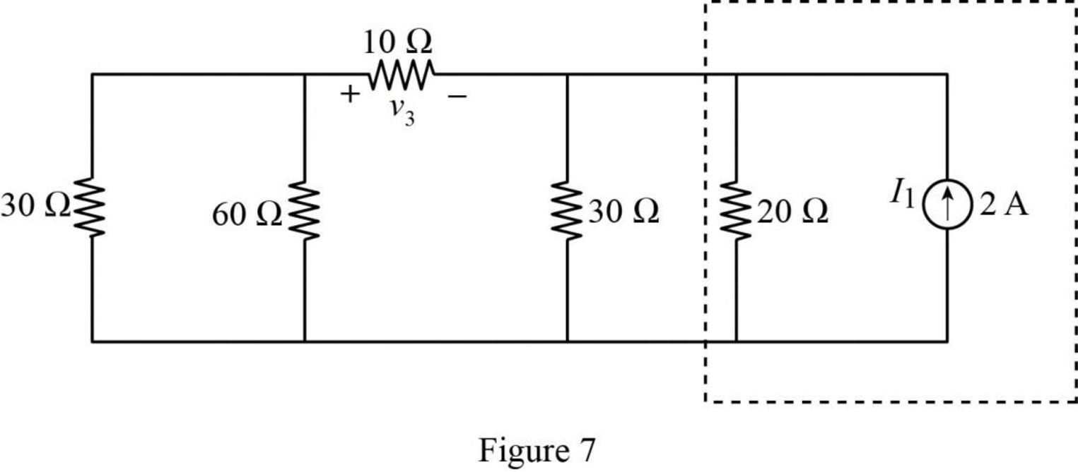
In Figure 7,
Similarly,
The modified Figure is shown in Figure 8.
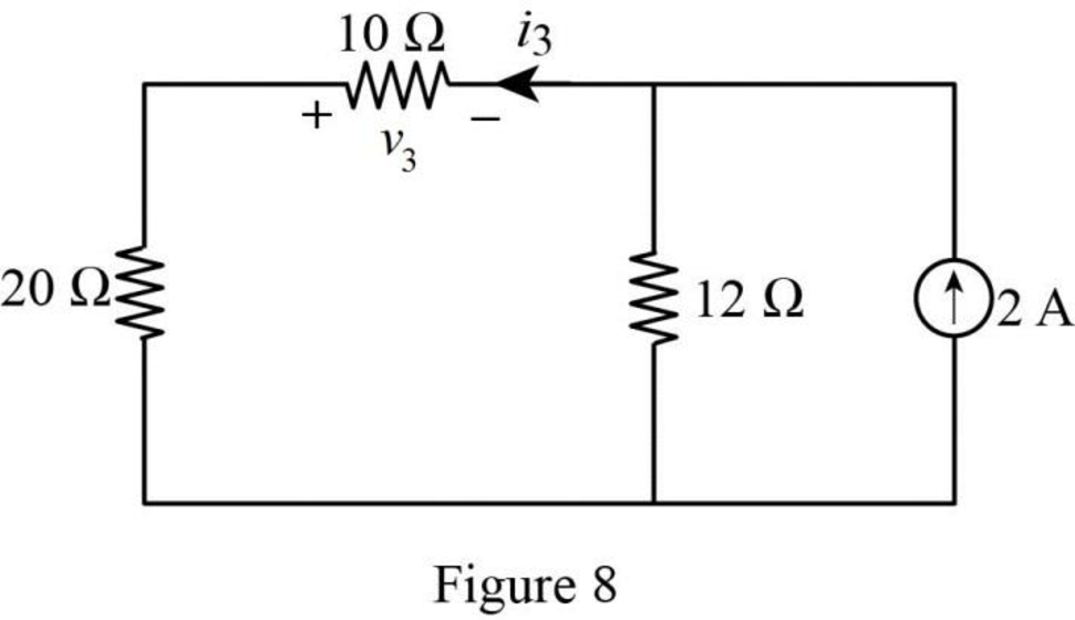
In Figure 8, the current
The voltage
Substitute
The total voltage
Substitute
PSPICE Simulation:
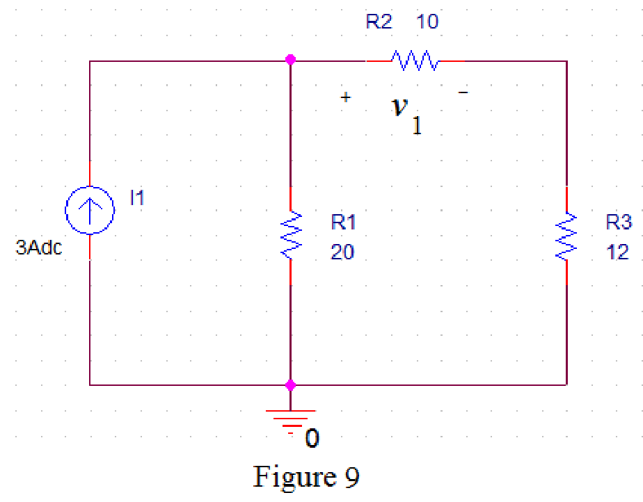
Refer to Figure 3, when
Draw the circuit diagram in PSPICE as shown in Figure 9.
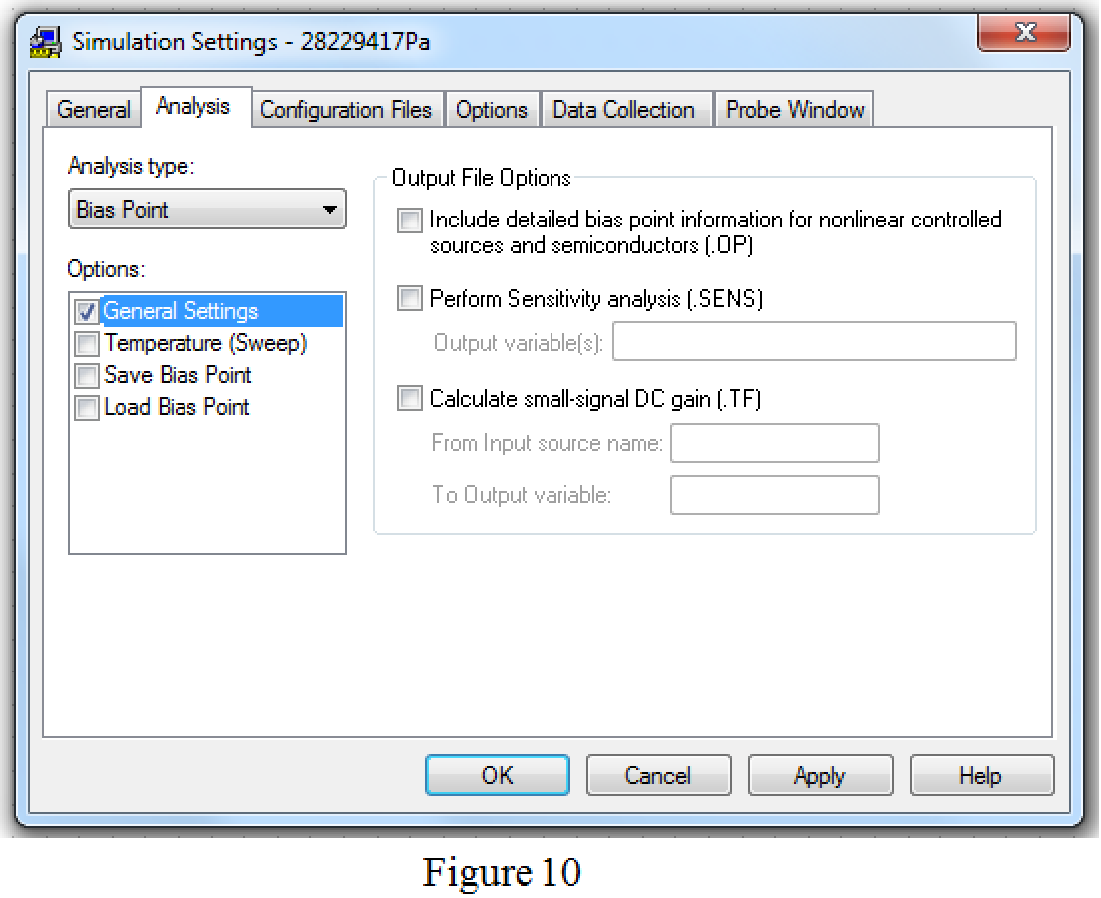
Save the circuit and provide the Simulation Settings as shown in Figure 10.
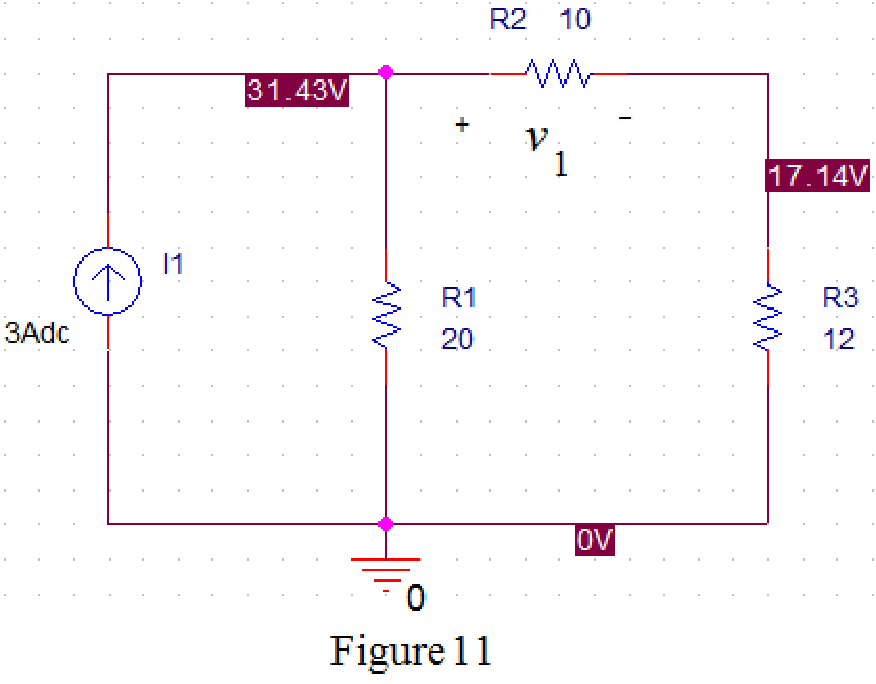
Now run the simulation and the results will be displayed as shown in Figure 11 by enabling “Enable Bias Voltage Display” icon.
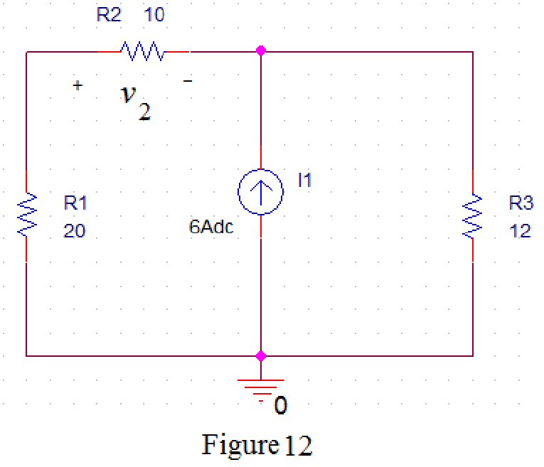
Refer to Figure 5, when
Draw the circuit diagram in PSPICE as shown in Figure 12.
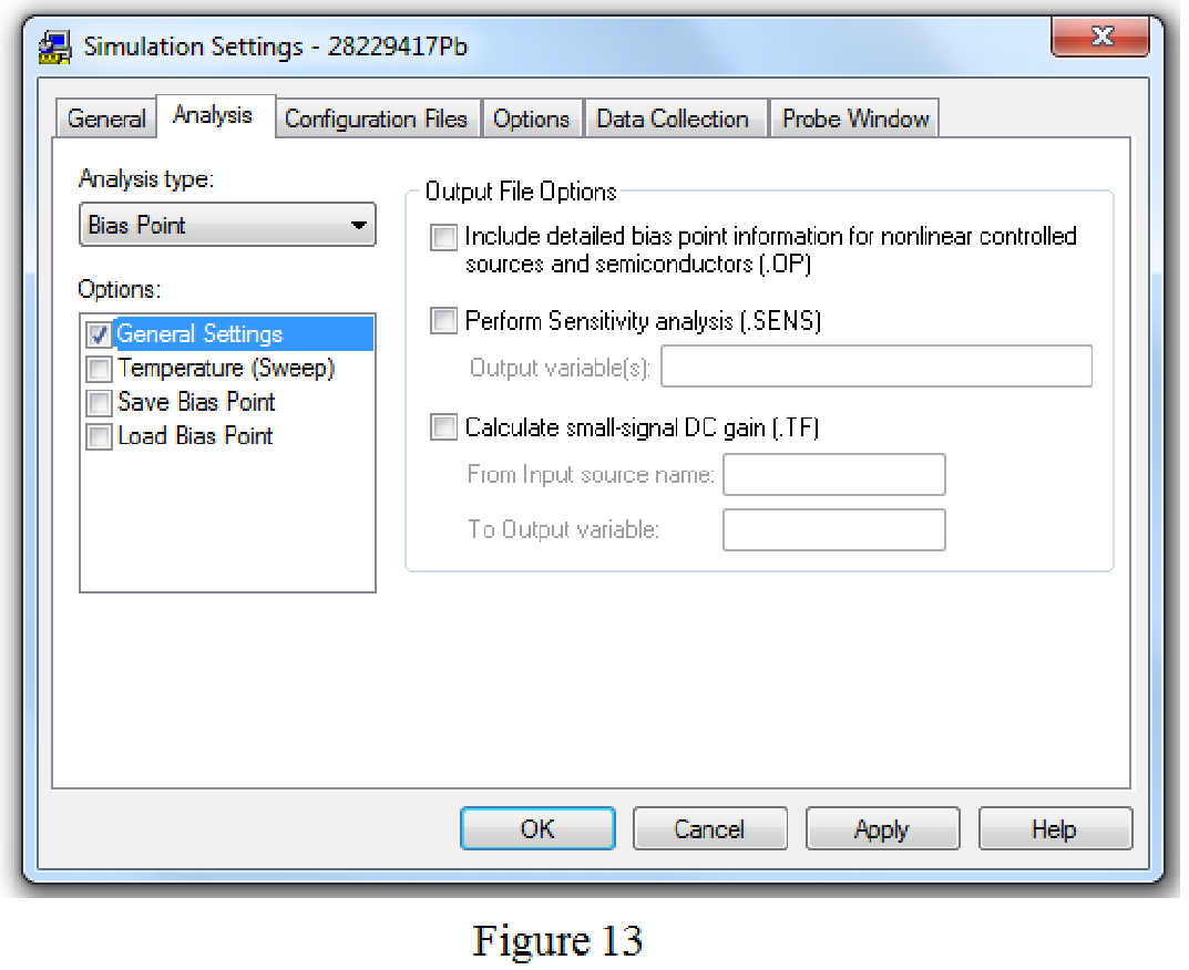
Save the circuit and provide the Simulation Settings as shown in Figure 13.
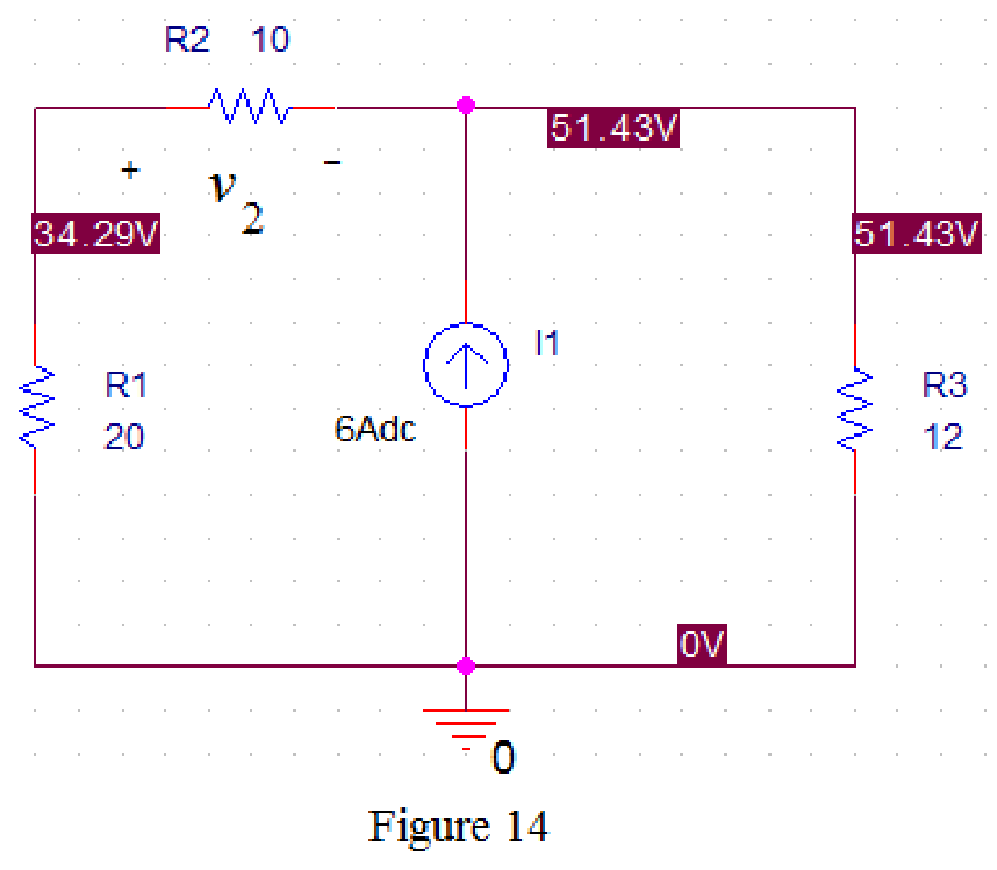
Now run the simulation and the results will be displayed as shown in Figure 14 by enabling “Enable Bias Voltage Display” icon.
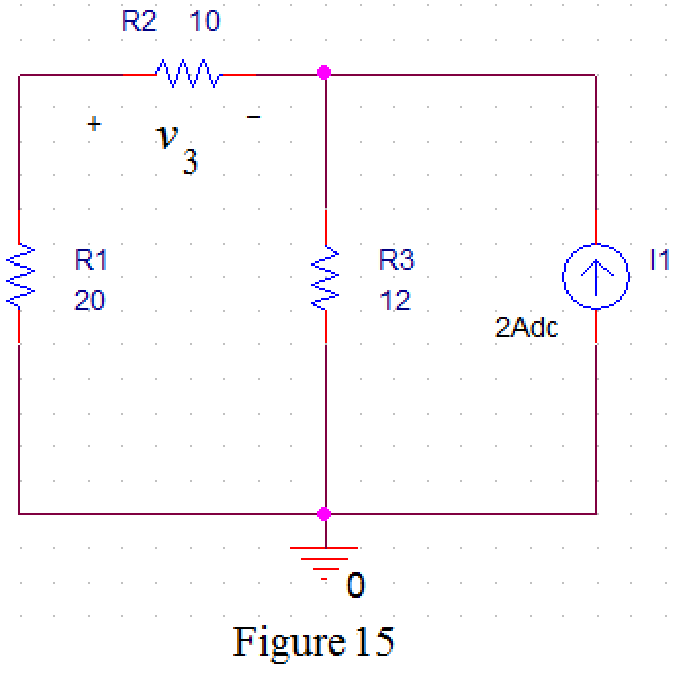
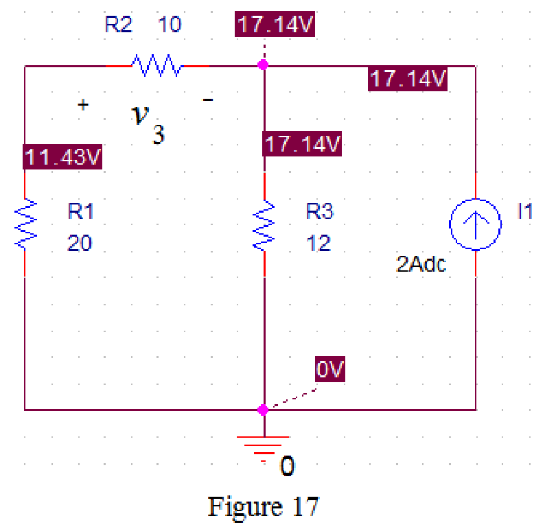
Refer to Figure 8, when
Draw the circuit diagram in PSPICE as shown in Figure 15.
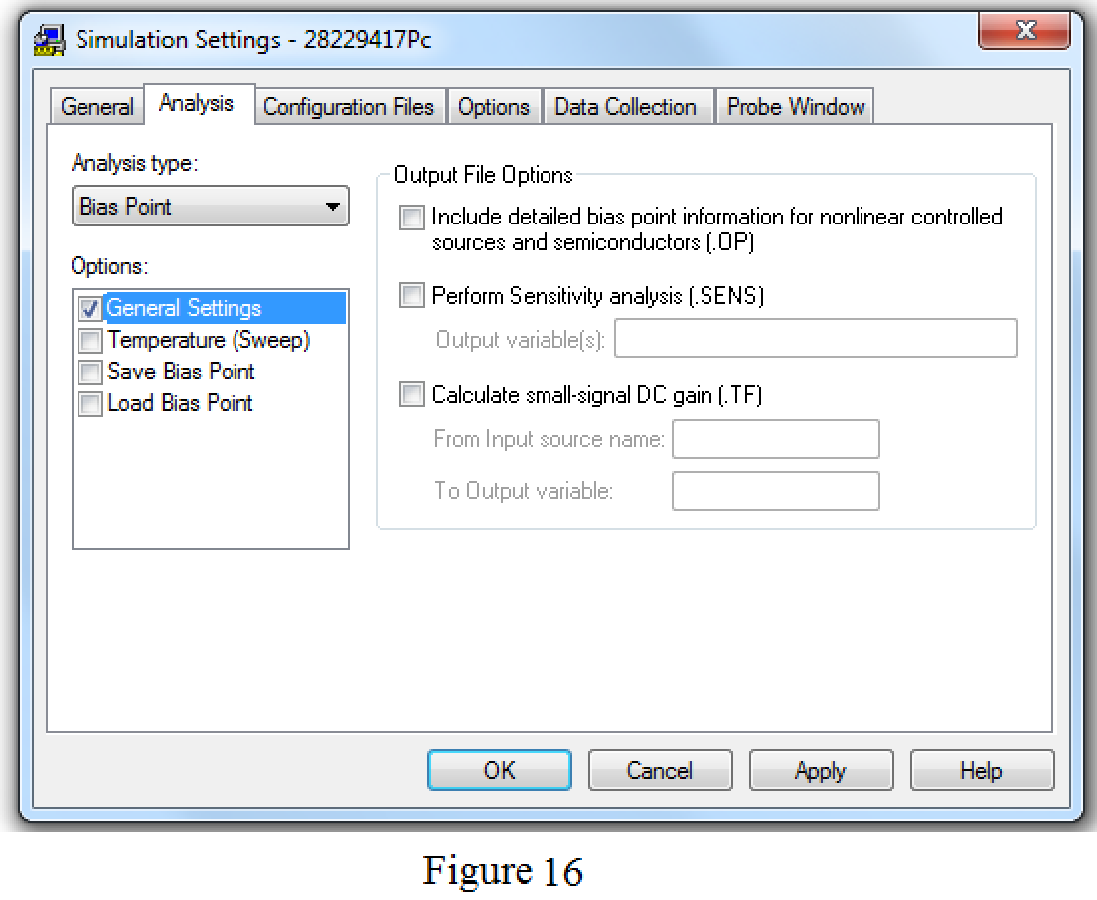
Save the circuit and provide the Simulation Settings as shown in Figure 16.
Now run the simulation and the results will be displayed as shown in Figure 17 by enabling “Enable Bias Voltage Display” icon.
From Figure 11, the voltage
From Figure 14, the voltage
From Figure 17, the voltage
Substitute
Conclusion:
Thus, the value of the voltage
Want to see more full solutions like this?
Chapter 4 Solutions
EBK FUNDAMENTALS OF ELECTRIC CIRCUITS
Additional Engineering Textbook Solutions
Electric machinery fundamentals
Fundamentals of Applied Electromagnetics (7th Edition)
ANALYSIS+DESIGN OF LINEAR CIRCUITS(LL)
Loose Leaf for Engineering Circuit Analysis Format: Loose-leaf
Electronics Fundamentals: Circuits, Devices & Applications
Principles and Applications of Electrical Engineering


- 4.17 Use superposition to obtain v, in the circuit of # Fig. 4.85. Check your result using PSpice or ML MultiSim. 30 Ω 10 Ω 20 Ω ww ww- ww + v, 90 V 60 Ω 6 A 30 Ω 40 V Figure 4.85 For Prob. 4.17.arrow_forwardIf we want to connect a voltage source with two resistors (either in series or in parallel) then voltage drop across the resistor R1 and the voltage across the resistor R2 ( if R1= R,= 10N) will be the same whether they are connected in series or in parallel. Select one: O True False < o Oarrow_forwardUse Thevenin’s theorem to find V0 in Prob. 4.12arrow_forward
- Determine Vx using the superposition principlearrow_forwardB The output of the following circuit is: 5V 4kQ2 (AB)' O iBx2 kn OV iB 214 QIB o5V 2kQ2 -O Y = ABarrow_forwardUsing the Thevenin's theorem, solve for the value of ETH based from the given figure: * R1 10 R2 5 R3 RL1 10V 10 O 5 V O 10 V 15 V O 20 Varrow_forward
- Q4. For the below circuit, determine: (a) The Thevenin equivalent circuit as seen from a-b. (b) The value of R and Ps for maximum power transfer to R₁ 40V 402 m 292 m 1210 a b R₁arrow_forwardDesign a voltage divider circuit (with a bleeder current of 20mA) that operates from a 500V source to supply the following loads: a) 400V @ 100mA b) 200V @ 50mA c) 100V @ 30mAarrow_forwardUse superposition to obtain vx in the circuit of Fig. 4.85.arrow_forward
- 4.8 Using superposition, find V, in the circuit of Fig. 4.76. Check with PSpice or MultiSim. Vo 12 3 V 9 V Figure 4.76 For Prob. 4.8. wwarrow_forwardThe equivalent resistance RAB in the above circuit = 50 Q 100 2 A 150 Q Select one: O a. 150 2 O b. 300 2 OC. 75 2 O d. 50 2arrow_forwardSUPERPOSITION THEOREM ACTIVITY Find the current through the 5 ohms, 6 ohms and 3 ohms resistors. Also find the voltage drop across the three resistors. Use the superposition theorem in solving the currents and voltages. S thr 6Ω ww + 20 V 40 V www.elecrically4u.comarrow_forward
 Introductory Circuit Analysis (13th Edition)Electrical EngineeringISBN:9780133923605Author:Robert L. BoylestadPublisher:PEARSON
 Delmar's Standard Textbook Of ElectricityElectrical EngineeringISBN:9781337900348Author:Stephen L. HermanPublisher:Cengage Learning
 Programmable Logic ControllersElectrical EngineeringISBN:9780073373843Author:Frank D. PetruzellaPublisher:McGraw-Hill Education
 Fundamentals of Electric CircuitsElectrical EngineeringISBN:9780078028229Author:Charles K Alexander, Matthew SadikuPublisher:McGraw-Hill Education
 Electric Circuits. (11th Edition)Electrical EngineeringISBN:9780134746968Author:James W. Nilsson, Susan RiedelPublisher:PEARSON
 Engineering ElectromagneticsElectrical EngineeringISBN:9780078028151Author:Hayt, William H. (william Hart), Jr, BUCK, John A.Publisher:Mcgraw-hill Education,