
Videos
A light-sensing circuit is in Fig. 4.90, including a resistor that changes value under illumination (photoresistor Rlight) and a variable resistor (potentiometer Rpot). The circuit is in the Wheatstone bridge configuration such that a “balanced” condition results in Vout = 0 for a defined value of incident light and a corresponding value for Rlight. (a) Derive an algebraic expression for Vout in terms of RS, R1, R2, Rlight, and Rpot. (b) Using the numerical values given in the circuit, calculate the value of Rpot required to balance the circuit at 500 lux, where Rlight = 200 Ω. (c) If the resistance of the photoresistor decreases by 2% for a light increase to 600 lux (and assuming the resistance change with light is linear), what will the light level be if you measure Vout = 150 mV?
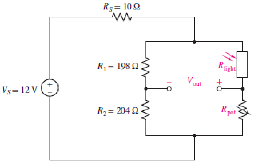
■ FIGURE 4.90
(a)
Write an algebraic expression for the output voltage
Explanation of Solution
Given data:
Refer to Figure 4.90 in the textbook.
Calculation:
The given circuit of Figure 4.90 is redrawn as shown in Figure 1.
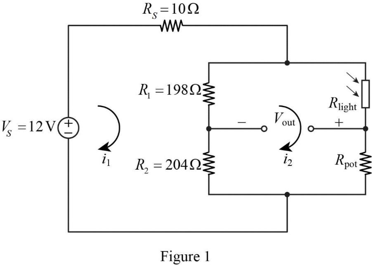
Apply Kirchhoff’s voltage law for the loop current
Apply Kirchhoff’s voltage law for the loop current
Rearrange the equation as follows,
Substitute equation (2) in equation (1).
Rearrange the equation as follows,
Substitute equation (3) in equation (2).
In Figure 1, the output voltage
Substitute equation (3) and (4) in equation (5).
Conclusion:
Thus, the output voltage
(b)
Calculate the value of variable resistor
Answer to Problem 74E
The value of variable resistor
Explanation of Solution
Given data:
Refer to Part (a).
The resistance
For balanced condition,
Calculation:
Refer to Part (a).
Substitute 0 for
Simplify the equation as follows,
Substitute
Conclusion:
Thus, the value of variable resistor
(c)
Find the light level if the resistance of the photoresistor decreases by 2% for a light increase to 600 lux with the measure of output voltage
Answer to Problem 74E
The light level is 760 lux if the resistance of the photoresistor decreases by 2% for a light increase to 600 lux with the measure of output voltage
Explanation of Solution
Given data:
Refer to Part (b).
The variable resistor
The output voltage
Calculation:
When the photoresistor resistance decreases by 2% with a light increase to 600 lux, then
Refer to Part (a), reduce the equation (6) as follows,
Substitute 12 V for
Reduce the equation as follows,
For a linear change, the light level is calculated as follows.
Conclusion:
Thus, the light level is 760 lux if the resistance of the photoresistor decreases by 2% for a light increase to 600 lux with the measure of output voltage
Want to see more full solutions like this?
Chapter 4 Solutions
Loose Leaf for Engineering Circuit Analysis Format: Loose-leaf
Additional Engineering Textbook Solutions
BASIC BIOMECHANICS
Vector Mechanics for Engineers: Statics
Modern Database Management
SURVEY OF OPERATING SYSTEMS
Starting Out With Visual Basic (8th Edition)
Electric Circuits. (11th Edition)


- Please solve in detailarrow_forward6.7 The transmitting aerial shown in Fig. Q.3 is supplied with current at 80 A peak and at frequency 666.66 kHz. Calculate (a) the effective height of the aerial, and (b) the electric field strength produced at ground level 40 km away. 60 m Fig. Q.3 Input 48 m Eartharrow_forwardox SIM 12.11 Consider the class B output stage, using MOSFETs, shown in Fig. P12.11. Let the devices have |V|= 0.5 V and μC WIL = 2 mA/V². With a 10-kHz sine-wave input of 5-V peak and a high value of load resistance, what peak output would you expect? What fraction of the sine-wave period does the crossover interval represent? For what value of load resistor is the peak output voltage reduced to half the input? Figure P12.11 +5 V Q1 Q2 -5Varrow_forward
- 4 H ་་་་་་་ 四一周 A H₂ Find out put c I writ R as a function G, H, Harrow_forward4 H A H₂ 四一周 Find out put c I writ R as a function G, H, Harrow_forward8. (a) In a Round-Robin tournament, the Tigers beat the Blue Jays, the Tigers beat the Cardinals, the Tigers beat the Orioles, the Blue Jays beat the Cardinals, the Blue Jays beat the Orioles and the Cardinals beat the Orioles. Model this outcome with a directed graph. https://www.akubihar.com (b) (c) ✓ - Let G = (V, E) be a simple graph. Let R be the relation on V consisting of pairs of vertices (u, v) such that there is a path from u to vor such that u= v. Show that R is an equivalence relation. 3 3 Determine whether the following given pair of directed graphs, shown in Fig. 1 and Fig. 2, are isomorphic or not. Exhibit an isomorphism or provide a rigorous argument that none exists. 4+4=8 Աշ աշ ИНИЯ Fig. 1 Fig. 2 Querarrow_forward
- EXAMPLE 4.5 Objective: Determine ID, circuit. V SG' SD Vs and the small - signal voltage gain of a PMOS transistor Consider the circuit shown in Figure 4.20(a). The transistor parameters are A K = 0.80m- V Р _2’TP = 0.5V, and λ = 0 Varrow_forwardNeed a solution and don't use chatgptarrow_forwardNeed a solarrow_forward
 Introductory Circuit Analysis (13th Edition)Electrical EngineeringISBN:9780133923605Author:Robert L. BoylestadPublisher:PEARSON
 Delmar's Standard Textbook Of ElectricityElectrical EngineeringISBN:9781337900348Author:Stephen L. HermanPublisher:Cengage Learning
 Programmable Logic ControllersElectrical EngineeringISBN:9780073373843Author:Frank D. PetruzellaPublisher:McGraw-Hill Education
 Fundamentals of Electric CircuitsElectrical EngineeringISBN:9780078028229Author:Charles K Alexander, Matthew SadikuPublisher:McGraw-Hill Education
 Electric Circuits. (11th Edition)Electrical EngineeringISBN:9780134746968Author:James W. Nilsson, Susan RiedelPublisher:PEARSON
 Engineering ElectromagneticsElectrical EngineeringISBN:9780078028151Author:Hayt, William H. (william Hart), Jr, BUCK, John A.Publisher:Mcgraw-hill Education,