Concept explainers
Consider steady, incompressible, two-dimensional shear flow for which the velocity field is
(a) In similar fashion, calculate the location of each of the other three corners of the fluid particle at time t+dt.
(b) From the fundamental definition of linear strain rate (the rate of increase in length per unit length), calculate linear strain rates
(c) Compare your results with those obtained from the equations for
(a)
The location of each of the other three corners of the fluid particle at time
Answer to Problem 66P
The location of the lower left corner after time
The location of the lower right corner after time
The location of the upper left corner after time
The location of the upper right corner after time
Explanation of Solution
Given information:
Two-dimensional shear flow, flow is incompressible, the velocity field is
Write the expression for the two-dimensional velocity field in the vector form.
Here, the constants are
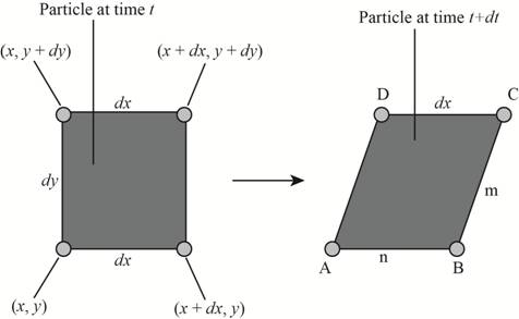
The following figure shows the position of the corners at time

Figure-(1)
Here, the length of the lower edge at time
Write the expression for location of the lower left corner after time
Write the expression for location of the lower right corner after time
Write the expression for location of the upper left corner after time
Write the expression for location of the upper right corner after time
Write the expression for velocity along x direction.
Calculation:
Substitute
Substitute
Substitute
Substitute
Conclusion:
The location of the lower left corner after time
The location of the lower right corner after time
The location of the upper left corner after time
The location of the upper right corner after time
(b)
The linear strain rates.
Answer to Problem 66P
The linear strain rate along x axis is
The linear strain rate along y axis is
Explanation of Solution
Write the expression for the strain rate along x direction.
Write the expression for the strain rate along y direction.
Write the expression for the length of the lower edge at time
Write the expression for the length of the lower edge at time
Calculation:
Substitute
Substitute
Substitute
Conclusion:
The linear strain rate along x axis is
The linear strain rate along y axis is
(c)
The linear strain rates in Cartesian coordinates.
Comparison of the linear strain rate by fundamental principal to the linear strain rates in Cartesian coordinates.
Answer to Problem 66P
The linear strain rate in Cartesian coordinates along x axis is
The linear strain rate in Cartesian coordinates along y axis is
The linear strain rate by fundamental principal and the linear strain rates in Cartesian coordinates are same
Explanation of Solution
Given information:
Linear strain along x axis is
Write the expression for the velocity along y direction.
Write the expression for the linear strain rate along x direction in Cartesian coordination.
Write the expression for the linear strain rate along y direction in Cartesian coordination.
Calculation:
Substitute
Substitute
Conclusion:
The linear strain rate in Cartesian coordinates along x axis is
The linear strain rate in Cartesian coordinates along y axis is
The linear strain rate by fundamental principal and the linear strain rates in Cartesian coordinates are the same.
Want to see more full solutions like this?
Chapter 4 Solutions
FLUID MECHANICS FUNDAMENTALS+APPS
- I need the answer as soon as possiblearrow_forwardAn incompressible velocity field is given by u=a(x°y²-y), v unknown, w=bxyz where a and b are constants. (a)What is the form of the velocity component for that the flow conserves mass? (b) Write Navier- Stokes's equation in 2-dimensional space with x-y coordinate system.arrow_forwardA common flow encountered in practice is the crossflow of a fluid approaching a long cylinder of radius R at a free stream speed of U∞. For incompressible inviscid flow, the velocity field of the flow is given as in fig. Show that the velocity field satisfies the continuity equation, and determine the stream function corresponding to this velocity field.arrow_forward
- THREE DIMENSIONAL ( NEED NEAT HANDWRITTEN SOLUTION ONLY OTHERWISE DOWNVOTE).arrow_forwardThis question is from the subject "Fluid Mechanics"arrow_forwardV u-v Question 4: Consider fully developed Couette flow - flow between two infinite parallel plates separated by distance h, with the top plate moving and the bottom plate stationary as illustrated. The flow is steady, incompressible, and two dimensional in the xy-plane. The velocity field is given by V = (u,v) = (V y/h)ỉ + 0ỷ, Generate an expression for stream function Yalong the vertical dashed line in the figure. For convenience, 4= 0 along the bottom wall of the channel. What is the value of Y along the top wall?arrow_forward
- Find the vorticity of the fluid motion for the given velocity com- ponents. KINEMATICS OF FLUIDS (a) u A(x + y), v = - A(x + y) (b) u = 2Axz, (c) u Ay²+ By + C, v = A(c² + x² - z²) 1)=0arrow_forwardIn a 2D dimension incompressible flow , if the fluid velocity components are given by u = x-4y , v = -4x then stream function y is given byarrow_forwardpls answer question with steparrow_forward
 Elements Of ElectromagneticsMechanical EngineeringISBN:9780190698614Author:Sadiku, Matthew N. O.Publisher:Oxford University Press
 Mechanics of Materials (10th Edition)Mechanical EngineeringISBN:9780134319650Author:Russell C. HibbelerPublisher:PEARSON
 Thermodynamics: An Engineering ApproachMechanical EngineeringISBN:9781259822674Author:Yunus A. Cengel Dr., Michael A. BolesPublisher:McGraw-Hill Education
 Control Systems EngineeringMechanical EngineeringISBN:9781118170519Author:Norman S. NisePublisher:WILEY
 Mechanics of Materials (MindTap Course List)Mechanical EngineeringISBN:9781337093347Author:Barry J. Goodno, James M. GerePublisher:Cengage Learning
 Engineering Mechanics: StaticsMechanical EngineeringISBN:9781118807330Author:James L. Meriam, L. G. Kraige, J. N. BoltonPublisher:WILEY


