
Engineering Circuit Analysis
9th Edition
ISBN: 9780073545516
Author: Hayt, William H. (william Hart), Jr, Kemmerly, Jack E. (jack Ellsworth), Durbin, Steven M.
Publisher: Mcgraw-hill Education,
expand_more
expand_more
format_list_bulleted
Concept explainers
Videos
Textbook Question
Chapter 4, Problem 5E
In the circuit of Fig. 4.35, determine the current labeled i with the assistance of nodal analysis techniques.
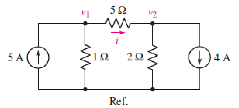
FIGURE 4.35
Expert Solution & Answer
Want to see the full answer?
Check out a sample textbook solution
Students have asked these similar questions
Given the information appearing in Fig. 4.74, determine:
(a) Ic.
(b) Rc.
(c) Rg-
(d) VCE-
12 V
Ic
RC
RB
O Vc = 6 V
VCE B= 80
IB= 40 µA
Using the nodal-analysis, calculate Vo and Paos2 in Figure Q4.
8002
20Ω
40Ω
b
V.
75V
6A
2002
50Ω
Figure Q4
4.70 An automobile battery, when connected to a car
radio, provides 12.5 V to the radio. When connected
to a set of headlights, it provides 11.7 V to the head-
lights. Assume the radio can be modeled as a 6.25 N
resistor and the headlights can be modeled as a
0.65 N resistor. What are the Thévenin and Norton
equivalents for the battery?
Chapter 4 Solutions
Engineering Circuit Analysis
Ch. 4.1 - For the circuit of Fig. 4.3, determine the nodal...Ch. 4.1 - For the circuit of Fig. 4.5, compute the voltage...Ch. 4.1 - For the circuit of Fig. 4.8, determine the nodal...Ch. 4.2 - For the circuit of Fig. 4.11, compute the voltage...Ch. 4.3 - Determine i1 and i2 in the circuit in Fig. 4.19....Ch. 4.3 - Determine i1 and i2 in the circuit of Fig 4.21....Ch. 4.3 - Determine i1 in the circuit of Fig. 4.24 if the...Ch. 4.4 - Determine the current i1 in the circuit of Fig....Ch. 4.4 - Determine v3 in the circuit of Fig. 4.28. FIGURE...Ch. 4 - Solve the following systems of equations: (a) 2v2 ...
Ch. 4 - (a) Solve the following system of equations:...Ch. 4 - (a) Solve the following system of equations:...Ch. 4 - Correct (and verify by running) the following...Ch. 4 - In the circuit of Fig. 4.35, determine the current...Ch. 4 - Calculate the power dissipated in the 1 resistor...Ch. 4 - For the circuit in Fig. 4.37, determine the value...Ch. 4 - With the assistance of nodal analysis, determine...Ch. 4 - Prob. 9ECh. 4 - For the circuit of Fig. 4.40, determine the value...Ch. 4 - Use nodal analysis to find vP in the circuit shown...Ch. 4 - Prob. 12ECh. 4 - Prob. 13ECh. 4 - Determine a numerical value for each nodal voltage...Ch. 4 - Prob. 15ECh. 4 - Using nodal analysis as appropriate, determine the...Ch. 4 - Prob. 17ECh. 4 - Determine the nodal voltages as labeled in Fig....Ch. 4 - Prob. 19ECh. 4 - Prob. 20ECh. 4 - Employing supernode/nodal analysis techniques as...Ch. 4 - Prob. 22ECh. 4 - Prob. 23ECh. 4 - Prob. 24ECh. 4 - Repeat Exercise 23 for the case where the 12 V...Ch. 4 - Prob. 26ECh. 4 - Prob. 27ECh. 4 - Determine the value of k that will result in vx...Ch. 4 - Prob. 29ECh. 4 - Prob. 30ECh. 4 - Prob. 31ECh. 4 - Determine the currents flowing out of the positive...Ch. 4 - Obtain numerical values for the two mesh currents...Ch. 4 - Use mesh analysis as appropriate to determine the...Ch. 4 - Prob. 35ECh. 4 - Prob. 36ECh. 4 - Find the unknown voltage vx in the circuit in Fig....Ch. 4 - Prob. 38ECh. 4 - Prob. 39ECh. 4 - Determine the power dissipated in the 4 resistor...Ch. 4 - (a) Employ mesh analysis to determine the power...Ch. 4 - Define three clockwise mesh currents for the...Ch. 4 - Prob. 43ECh. 4 - Prob. 44ECh. 4 - Prob. 45ECh. 4 - Prob. 46ECh. 4 - Prob. 47ECh. 4 - Prob. 48ECh. 4 - Prob. 49ECh. 4 - Prob. 50ECh. 4 - Prob. 51ECh. 4 - Prob. 52ECh. 4 - For the circuit represented schematically in Fig....Ch. 4 - The circuit of Fig. 4.80 is modified such that the...Ch. 4 - The circuit of Fig. 4.81 contains three sources....Ch. 4 - Solve for the voltage vx as labeled in the circuit...Ch. 4 - Consider the five-source circuit of Fig. 4.83....Ch. 4 - Replace the dependent voltage source in the...Ch. 4 - After studying the circuit of Fig. 4.84, determine...Ch. 4 - Prob. 60ECh. 4 - Employ LTspice (or similar CAD tool) to verify the...Ch. 4 - Employ LTspice (or similar CAD tool) to verify the...Ch. 4 - Employ LTspice (or similar CAD tool) to verify the...Ch. 4 - Verify numerical values for each nodal voltage in...Ch. 4 - Prob. 65ECh. 4 - Prob. 66ECh. 4 - Prob. 67ECh. 4 - Prob. 68ECh. 4 - Prob. 69ECh. 4 - (a) Under what circumstances does the presence of...Ch. 4 - Referring to Fig. 4.88, (a) determine whether...Ch. 4 - Consider the LED circuit containing a red, green,...Ch. 4 - The LED circuit in Fig. 4.89 is used to mix colors...Ch. 4 - A light-sensing circuit is in Fig. 4.90, including...Ch. 4 - Use SPICE to analyze the circuit in Exercise 74 by...
Knowledge Booster


Learn more about
Need a deep-dive on the concept behind this application? Look no further. Learn more about this topic, electrical-engineering and related others by exploring similar questions and additional content below.Similar questions
- 4.1.Part A: Ohm's law This part aims at checking and proving Ohm's law. Using the fixed 5 V output from the power supply, the 1k, 2k2 and 5k resistors, and considering all the possible unique circuit combinations with these 3 resistors only, conduct the followings: 1. Before the lab session and manually a) design and manually sketch your various circuits using the fixed 5 V power supply (i.e. put the resistors in various parallel or series combinations), b) calculate the current (immediately after the power supply) for all your circuits and find the current and the power dissipated in each of the 3 resistors, c) rank the circuits from maximum to minimum current observed immediately after the power supply, and d) prepare your report and have it with you electronically at the time of your lab session. 2. Before the lab session, and using the LushProjects simulator (see above URL) a) make simulation files and simulate all your circuits, b) check and compare the results with the manual…arrow_forwardQ5 Draw the output voltage waveform for each circuit in Fig. 4.30 with respect the input. Show voltage levels. +1 V +1 V 0- -I V +2 V Vunmuy = 18 V Vrtmna = 110 V %3D -2 V (a) (b)arrow_forwarda. Using KVL, complete the working equations for the clipping circuits shown in Fig. 4.11 for both positive and negative half-cycles of the input. Simple Parallel Clippers (ldeal Diodles) Biased Parallel Clippers tldeal Diodes) Figure 4.11 Clipping Circuits (Parallel)arrow_forward
- c) Analyse the steady-state voltage vo(t) of the circuit in Figure Q4(b) if the input voltage is given by: v;(t) = 7.5 cos(2t - 122°) +2.2 cos(6t – 102°) +1.3 cos(10t – 97°) + 0.91 cos(14t – 95°) + ... V Show your answer for the first four terms of the output voltage, Vo(t).arrow_forwardAn attenuator is an interface circuit that reduces the voltage level without changing the output resistance. (a) By specifying R, and R, of the interface circuit in Fig. 4.150, design an attenuator that will meet the following requirements: V. 0.125, Vg Rea = RTh = Rg = 100 N (b) Using the interface designed in part (a), calculate the current through a load of R1 = 50 N when V = 12 V. R, Rp RL Load Attenuator Reg In part (a) determine the values of Rs and RP. ww wwwarrow_forward4.1 Find a Thévenin equivalent for the circuit shown with respect the 6 resistor. Use the Thévenin equivalent to find the current in the 6 2 resistor. If the 6 2 resistor were replaced with an 8 V source with positive terminal at the right, what would be the current in the source? 5 ohm w 40V 5 ohm 3 ohm 6 ohm ww 4 ohm 8 ohmarrow_forward
- 4.2 Use Mesh Analysis to find the values of Ix and Vx in the figure.arrow_forward(Example 4.8) Determine all node voltages and branch currents assuming = 100. Assume Active +5 V 100 ΚΩ www +10 V 2 ΚΩarrow_forward1. For the fixed-bias configuration of Fig. 4.118, determine: a. IBg' 16 V b. Icg c. VCEg Ico 1.8 k22 510 kQ2 VB IBQ Vc VCEQ B=120 VEarrow_forward
- Assume Ic=le Given the information provided in Fig. 4.78, determine: (a) Rc. (b) RE. (c) Rg- (d) VCE- (e) VB. 12 V ma 0 7.6 V B = 80 024 Varrow_forward(a) Simplify the circuit shown in Figure Q4 (a) into single voltage source by applying source transformation and determine the current, io. 3 A 6 A 20 V Figure Q4 (a)arrow_forward"NODAL VOLTAGE ANALYSIS" Please Find the Vo Using NODAL VOLTAGE ANALYSIS thankyou very much! I've included a cicruit app to check if your answer was correct and close to the value of currents and voltages which is 0.5V thankyou! I've been testing simple circuits to practice problems using different theorems,I appreciate you very much Thankyou!arrow_forward
arrow_back_ios
SEE MORE QUESTIONS
arrow_forward_ios
Recommended textbooks for you
 Introductory Circuit Analysis (13th Edition)Electrical EngineeringISBN:9780133923605Author:Robert L. BoylestadPublisher:PEARSON
 Delmar's Standard Textbook Of ElectricityElectrical EngineeringISBN:9781337900348Author:Stephen L. HermanPublisher:Cengage Learning
 Programmable Logic ControllersElectrical EngineeringISBN:9780073373843Author:Frank D. PetruzellaPublisher:McGraw-Hill Education
 Fundamentals of Electric CircuitsElectrical EngineeringISBN:9780078028229Author:Charles K Alexander, Matthew SadikuPublisher:McGraw-Hill Education
 Electric Circuits. (11th Edition)Electrical EngineeringISBN:9780134746968Author:James W. Nilsson, Susan RiedelPublisher:PEARSON
 Engineering ElectromagneticsElectrical EngineeringISBN:9780078028151Author:Hayt, William H. (william Hart), Jr, BUCK, John A.Publisher:Mcgraw-hill Education,
Introductory Circuit Analysis (13th Edition)
Electrical Engineering
ISBN:9780133923605
Author:Robert L. Boylestad
Publisher:PEARSON
Delmar's Standard Textbook Of Electricity
Electrical Engineering
ISBN:9781337900348
Author:Stephen L. Herman
Publisher:Cengage Learning
Programmable Logic Controllers
Electrical Engineering
ISBN:9780073373843
Author:Frank D. Petruzella
Publisher:McGraw-Hill Education
Fundamentals of Electric Circuits
Electrical Engineering
ISBN:9780078028229
Author:Charles K Alexander, Matthew Sadiku
Publisher:McGraw-Hill Education
Electric Circuits. (11th Edition)
Electrical Engineering
ISBN:9780134746968
Author:James W. Nilsson, Susan Riedel
Publisher:PEARSON
Engineering Electromagnetics
Electrical Engineering
ISBN:9780078028151
Author:Hayt, William H. (william Hart), Jr, BUCK, John A.
Publisher:Mcgraw-hill Education,
Nodal Analysis for Circuits Explained; Author: Engineer4Free;https://www.youtube.com/watch?v=f-sbANgw4fo;License: Standard Youtube License