
Engineering Circuit Analysis
9th Edition
ISBN: 9780073545516
Author: Hayt, William H. (william Hart), Jr, Kemmerly, Jack E. (jack Ellsworth), Durbin, Steven M.
Publisher: Mcgraw-hill Education,
expand_more
expand_more
format_list_bulleted
Concept explainers
Videos
Textbook Question
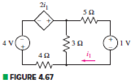
Chapter 4, Problem 40E
Determine the power dissipated in the 4 Ω resistor of the circuit shown in Fig. 4.67.
Expert Solution & Answer
Want to see the full answer?
Check out a sample textbook solution
Students have asked these similar questions
Q5 Draw the output voltage waveform for each circuit in Fig. 4.30 with respect to
the input. Show voltage levels.
+I V
+1 V
0-
-I V
+2 V
Vutmery = 18 V
-2 V
(a)
(b)
Obtain numerical values for the two mesh currents ij and iz in the circuit
shown in Fig. 4.61.
32
5 V
iz
12 V
14 2
4. Determine the value of the voltage labeled vi in Fig. 4.34.
IA
(()3 A
Chapter 4 Solutions
Engineering Circuit Analysis
Ch. 4.1 - For the circuit of Fig. 4.3, determine the nodal...Ch. 4.1 - For the circuit of Fig. 4.5, compute the voltage...Ch. 4.1 - For the circuit of Fig. 4.8, determine the nodal...Ch. 4.2 - For the circuit of Fig. 4.11, compute the voltage...Ch. 4.3 - Determine i1 and i2 in the circuit in Fig. 4.19....Ch. 4.3 - Determine i1 and i2 in the circuit of Fig 4.21....Ch. 4.3 - Determine i1 in the circuit of Fig. 4.24 if the...Ch. 4.4 - Determine the current i1 in the circuit of Fig....Ch. 4.4 - Determine v3 in the circuit of Fig. 4.28. FIGURE...Ch. 4 - Solve the following systems of equations: (a) 2v2 ...
Ch. 4 - (a) Solve the following system of equations:...Ch. 4 - (a) Solve the following system of equations:...Ch. 4 - Correct (and verify by running) the following...Ch. 4 - In the circuit of Fig. 4.35, determine the current...Ch. 4 - Calculate the power dissipated in the 1 resistor...Ch. 4 - For the circuit in Fig. 4.37, determine the value...Ch. 4 - With the assistance of nodal analysis, determine...Ch. 4 - Prob. 9ECh. 4 - For the circuit of Fig. 4.40, determine the value...Ch. 4 - Use nodal analysis to find vP in the circuit shown...Ch. 4 - Prob. 12ECh. 4 - Prob. 13ECh. 4 - Determine a numerical value for each nodal voltage...Ch. 4 - Prob. 15ECh. 4 - Using nodal analysis as appropriate, determine the...Ch. 4 - Prob. 17ECh. 4 - Determine the nodal voltages as labeled in Fig....Ch. 4 - Prob. 19ECh. 4 - Prob. 20ECh. 4 - Employing supernode/nodal analysis techniques as...Ch. 4 - Prob. 22ECh. 4 - Prob. 23ECh. 4 - Prob. 24ECh. 4 - Repeat Exercise 23 for the case where the 12 V...Ch. 4 - Prob. 26ECh. 4 - Prob. 27ECh. 4 - Determine the value of k that will result in vx...Ch. 4 - Prob. 29ECh. 4 - Prob. 30ECh. 4 - Prob. 31ECh. 4 - Determine the currents flowing out of the positive...Ch. 4 - Obtain numerical values for the two mesh currents...Ch. 4 - Use mesh analysis as appropriate to determine the...Ch. 4 - Prob. 35ECh. 4 - Prob. 36ECh. 4 - Find the unknown voltage vx in the circuit in Fig....Ch. 4 - Prob. 38ECh. 4 - Prob. 39ECh. 4 - Determine the power dissipated in the 4 resistor...Ch. 4 - (a) Employ mesh analysis to determine the power...Ch. 4 - Define three clockwise mesh currents for the...Ch. 4 - Prob. 43ECh. 4 - Prob. 44ECh. 4 - Prob. 45ECh. 4 - Prob. 46ECh. 4 - Prob. 47ECh. 4 - Prob. 48ECh. 4 - Prob. 49ECh. 4 - Prob. 50ECh. 4 - Prob. 51ECh. 4 - Prob. 52ECh. 4 - For the circuit represented schematically in Fig....Ch. 4 - The circuit of Fig. 4.80 is modified such that the...Ch. 4 - The circuit of Fig. 4.81 contains three sources....Ch. 4 - Solve for the voltage vx as labeled in the circuit...Ch. 4 - Consider the five-source circuit of Fig. 4.83....Ch. 4 - Replace the dependent voltage source in the...Ch. 4 - After studying the circuit of Fig. 4.84, determine...Ch. 4 - Prob. 60ECh. 4 - Employ LTspice (or similar CAD tool) to verify the...Ch. 4 - Employ LTspice (or similar CAD tool) to verify the...Ch. 4 - Employ LTspice (or similar CAD tool) to verify the...Ch. 4 - Verify numerical values for each nodal voltage in...Ch. 4 - Prob. 65ECh. 4 - Prob. 66ECh. 4 - Prob. 67ECh. 4 - Prob. 68ECh. 4 - Prob. 69ECh. 4 - (a) Under what circumstances does the presence of...Ch. 4 - Referring to Fig. 4.88, (a) determine whether...Ch. 4 - Consider the LED circuit containing a red, green,...Ch. 4 - The LED circuit in Fig. 4.89 is used to mix colors...Ch. 4 - A light-sensing circuit is in Fig. 4.90, including...Ch. 4 - Use SPICE to analyze the circuit in Exercise 74 by...
Knowledge Booster


Learn more about
Need a deep-dive on the concept behind this application? Look no further. Learn more about this topic, electrical-engineering and related others by exploring similar questions and additional content below.Similar questions
- 7. If the base resistor of Fig. 4.118 is increased to 910 kῼ, find the new Q -point and resultingvalues of ICQ and VCEQ.arrow_forwardQ5 Draw the output voltage waveform for each circuit in Fig. 4.30 with respect the input. Show voltage levels. +1 V +1 V 0- -I V +2 V Vunmuy = 18 V Vrtmna = 110 V %3D -2 V (a) (b)arrow_forwardGiven the information appearing in Fig. 4.74, determine: (a) Ic. (b) Rc. (c) Rg- (d) VCE- 12 V Ic RC RB O Vc = 6 V VCE B= 80 IB= 40 µAarrow_forward
- Find the Norton equivalent circuit for the circuit in Fig. 4.42, at terminals a-b.arrow_forwardIn the circuit shown in Fig.4, * the current through 82 is 5 0 10 V 10 2 10Ω Fig.4 1A O 0.5A 1.5A O 1.75Aarrow_forwardQ4: Find the Thevenin and Norton equivalent circuits for the circuit shown in Fig. 4 ww 60/ 25 V Figure 4arrow_forward
- Using Fig. 4.78, design a problem to help other students better understand superposition. Note, the letter k is a gain you can specify to make the problem easier to solve but must not be zeroarrow_forward4.70 An automobile battery, when connected to a car radio, provides 12.5 V to the radio. When connected to a set of headlights, it provides 11.7 V to the head- lights. Assume the radio can be modeled as a 6.25 N resistor and the headlights can be modeled as a 0.65 N resistor. What are the Thévenin and Norton equivalents for the battery?arrow_forwardFind the Norton equivalent circuit of the circuit in Fig. 4.45 at terminals a-h. 60 10 A 20 Figure 4.45 ww wwarrow_forward
arrow_back_ios
SEE MORE QUESTIONS
arrow_forward_ios
Recommended textbooks for you
 Introductory Circuit Analysis (13th Edition)Electrical EngineeringISBN:9780133923605Author:Robert L. BoylestadPublisher:PEARSON
 Delmar's Standard Textbook Of ElectricityElectrical EngineeringISBN:9781337900348Author:Stephen L. HermanPublisher:Cengage Learning
 Programmable Logic ControllersElectrical EngineeringISBN:9780073373843Author:Frank D. PetruzellaPublisher:McGraw-Hill Education
 Fundamentals of Electric CircuitsElectrical EngineeringISBN:9780078028229Author:Charles K Alexander, Matthew SadikuPublisher:McGraw-Hill Education
 Electric Circuits. (11th Edition)Electrical EngineeringISBN:9780134746968Author:James W. Nilsson, Susan RiedelPublisher:PEARSON
 Engineering ElectromagneticsElectrical EngineeringISBN:9780078028151Author:Hayt, William H. (william Hart), Jr, BUCK, John A.Publisher:Mcgraw-hill Education,
Introductory Circuit Analysis (13th Edition)
Electrical Engineering
ISBN:9780133923605
Author:Robert L. Boylestad
Publisher:PEARSON
Delmar's Standard Textbook Of Electricity
Electrical Engineering
ISBN:9781337900348
Author:Stephen L. Herman
Publisher:Cengage Learning
Programmable Logic Controllers
Electrical Engineering
ISBN:9780073373843
Author:Frank D. Petruzella
Publisher:McGraw-Hill Education
Fundamentals of Electric Circuits
Electrical Engineering
ISBN:9780078028229
Author:Charles K Alexander, Matthew Sadiku
Publisher:McGraw-Hill Education
Electric Circuits. (11th Edition)
Electrical Engineering
ISBN:9780134746968
Author:James W. Nilsson, Susan Riedel
Publisher:PEARSON
Engineering Electromagnetics
Electrical Engineering
ISBN:9780078028151
Author:Hayt, William H. (william Hart), Jr, BUCK, John A.
Publisher:Mcgraw-hill Education,
Norton's Theorem and Thevenin's Theorem - Electrical Circuit Analysis; Author: The Organic Chemistry Tutor;https://www.youtube.com/watch?v=-kkvqr1wSwA;License: Standard Youtube License