
Concept explainers
Videos
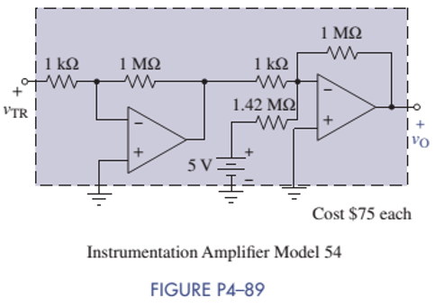
Your engineering firm needs an instrumentation amplifier that provides the following input-output relationship:
Want to see the full answer?
Check out a sample textbook solution
Chapter 4 Solutions
ANALYSIS+DESIGN OF LINEAR CIRCUITS(LL)


- In the circuit shown below what is the output voltage (Vout) if a silicon transistor Q and an ideal op-amp are used? Show solution on your answer sheet. +15 V 1kQ OVout 5 V -15 V O -0.7V O 0.7V O 15V O -15Varrow_forwardestion 4-) Show that the circuit given below is a noninverting integrator. Assume op amp is ideal. Vi +1 R R m C + R R W + voarrow_forward4. Calculate the output voltage of each of the following op-amp circuit. X1 Hop thi -1.5V Y11V R3 1kQ VCC 15.0V VEE -15.0V U1 -741 VCC 15.0V VEE -15.0V R4 2kQ 741 U2 R1 22.210. R2 • 1 ΚΩ ww/li R5 ww 1kQ R6 1kQ VCC 15:0V VEE -15.0V R7 1k0 U3 741 VOUTarrow_forward
- It is desired to add the two input voltages of the Op-Amp below. Decide what values of resistors should be used. R V+ R. R V-arrow_forwardProblem 4. One of the applications of the op-amp is a comparator. Determine the output of the op-amp in each case below and justify your answer. 9V +9V +9V 2V 2V 6V Vout Vout Vout 4V 4V 4V ov -9V -9V (c) (b) (a) Vout = Vout = Vout =arrow_forwardDesign op-amp ciran't produce Even odd to each of following outputs. -026=0-42₂ - 10%, @v₂ = 84 — 32/₂₁ +423-924 (2) V = V₁ + V₂ - 2013 @ 2 = 252₁ +32 Vaarrow_forward
- Q4.Consider the circuit in Figure 4. Assume ideal op-amps are used. The input voltage is v/ 0.5 sin(co t). +=10|1 12 kQ 12 km2 www 12kQ2 www 12 kQ ww (a) Determine the voltagevos 40 ΚΩ 30 kQ2 Figure 4 VOB + VOC 10-1₁ VOarrow_forwardR1=5k, R2= 6k, R3=200, and R4=500. What is the output current from this op amp if Vin =-10V? R2 R1 IOP1 VE1 R3 Vin R4arrow_forwardDesign an op-amp circuit to yield the relationship shown in each equation. Vo = V1 + 10V2 – 30V3 – 100 V4a.) Rmin = 6kΩb.) Rin = 6kΩarrow_forward
- Part A Find it in the circuit in. Suppose R = 6 kn. The op amp in the circuit is ideal. Express your answer in milliamperes to three significant figures. You did not open hints for this part. ANSWER: iL = mA 5V 3 ΚΩ www 10 ΚΩ 6 k -w {5 ΚΩ 20 V D -20 Varrow_forwardWhat is the voltage at node a for this ideal op-amp configuration? a ov, 10V R3 R1- 1kO R2= 2kQ Vo 20V -20Varrow_forwardQuestion - Design a circuit according to figure using 4:1 multiplexerarrow_forward
 Introductory Circuit Analysis (13th Edition)Electrical EngineeringISBN:9780133923605Author:Robert L. BoylestadPublisher:PEARSON
 Delmar's Standard Textbook Of ElectricityElectrical EngineeringISBN:9781337900348Author:Stephen L. HermanPublisher:Cengage Learning
 Programmable Logic ControllersElectrical EngineeringISBN:9780073373843Author:Frank D. PetruzellaPublisher:McGraw-Hill Education
 Fundamentals of Electric CircuitsElectrical EngineeringISBN:9780078028229Author:Charles K Alexander, Matthew SadikuPublisher:McGraw-Hill Education
 Electric Circuits. (11th Edition)Electrical EngineeringISBN:9780134746968Author:James W. Nilsson, Susan RiedelPublisher:PEARSON
 Engineering ElectromagneticsElectrical EngineeringISBN:9780078028151Author:Hayt, William H. (william Hart), Jr, BUCK, John A.Publisher:Mcgraw-hill Education,