
ANALYSIS+DESIGN OF LINEAR CIRCUITS(LL)
8th Edition
ISBN: 9781119235385
Author: Thomas
Publisher: WILEY
expand_more
expand_more
format_list_bulleted
Concept explainers
Videos
Textbook Question
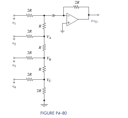
Chapter 4, Problem 4.80P
An
Expert Solution & Answer
Want to see the full answer?
Check out a sample textbook solution
Students have asked these similar questions
10 kN and R 30 kn. Assume that the op-
4-23. Consider the circuit of Figure P4-11 with R¡
amp slew rate is 0.5 V/us. Calculate the rise time TSR due to the slew rate when the input is
a pulse that changes from zero to each of the following values:
a. 0.2 V
b. 1 V
c. 3 V
SR = type your answer...
a) Tsr =
b) Tsr=
c) Tsr =
type your answer...
type your answer...
type your answer...
FIGURE P4-11
R₁
ww
+
Rfiq
ww
+
Vo
Given the circuit provided in Figure 4-30 (p. 194) and the fabrication parameters provided, find ID and VDS. VBias = 3.8V, VDD = 5V, RD= 1kΩ, RS = 1kΩ, Vt = 0.3V, kn = 100uA/V2. (NOTE: use Wolfram Alpha Equation Solver.) (b) Design a voltage divider circuit to create the bias voltage using resistors R1 and R2. Let the current through the voltage divider be in the range of 1mA to 10mA.
Hi i am trying to convert a pwm signal to a ramp signal, i have an output that currently generates around 26mA but I want a ramp current signal that will range between 0 -100mA depending on the duty cycle of the PWM .
so this means that the circuit should include an amplificator to get the current to 100mA.
can you please draw the circuit
thank you
Chapter 4 Solutions
ANALYSIS+DESIGN OF LINEAR CIRCUITS(LL)
Ch. 4 - Find the voltage gain vO/vS and current gain iO/ix...Ch. 4 - Prob. 4.2PCh. 4 - Prob. 4.3PCh. 4 - Prob. 4.4PCh. 4 - Find the voltage gain vO/vS in Figure P4-5.Ch. 4 - Find the voltage gain vO/vS in Figure P4-6.Ch. 4 - Find an expression for the current gain iO/iS in...Ch. 4 - Prob. 4.8PCh. 4 - Prob. 4.9PCh. 4 - Find an expression for the voltage gain vO/vs in...
Ch. 4 - Prob. 4.12PCh. 4 - In the circuit of Figure P4-13, the VCVS has of...Ch. 4 - Prob. 4.14PCh. 4 - (a) Find the Thévenin equivalent circuit that the...Ch. 4 - Prob. 4.16PCh. 4 - Prob. 4.18PCh. 4 - Prob. 4.19PCh. 4 - The circuit parameters in figure P4-21 are...Ch. 4 - The circuit parameters in Figure P4-21 are...Ch. 4 - The parameters of the transistor in Figure P4-23...Ch. 4 - Prob. 4.25PCh. 4 - Find the voltage gain of each OP AMP circuit shown...Ch. 4 - Considering simplicity and standard 10 tolerance...Ch. 4 - Two OP AMP circuits are shown in Figure P4-28....Ch. 4 - Prob. 4.29PCh. 4 - What is the range of the gain vO/vS in Figure...Ch. 4 - Using only one OP AMP, design a circuit that...Ch. 4 - Design a circuit using only one OP AMP that...Ch. 4 - Prob. 4.36PCh. 4 - For the circuit in Figure P4-37: (a) Find vO in...Ch. 4 - A young designer needed to amplify a 2-V signal by...Ch. 4 - Design two circuits to produce the following...Ch. 4 - Design a noninverting summer for five inputs with...Ch. 4 - For the circuit in Figure P4-41: Find vO in terms...Ch. 4 - The input-output relationship for a three-input...Ch. 4 - Find vo in terms of the inputs v1,v2, and v3 in...Ch. 4 - Prob. 4.44PCh. 4 - Prob. 4.45PCh. 4 - Prob. 4.46PCh. 4 - Prob. 4.47PCh. 4 - It is claimed that vO=vS when the switch is closed...Ch. 4 - Prob. 4.49PCh. 4 - Prob. 4.50PCh. 4 - Use node-voltage analysis in Figure P4-51 to show...Ch. 4 - Prob. 4.52PCh. 4 - Prob. 4.53PCh. 4 - For the block diagram of Figure P4-54: Find an...Ch. 4 - For the block diagram of Figure P4-55: Find an...Ch. 4 - For the circuit in Figure P4-56: Find vO in terms...Ch. 4 - Prob. 4.57PCh. 4 - Onan exam, students were asked to design an...Ch. 4 - Prob. 4.59PCh. 4 - For the circuit of Figure P4-60: Use node-voltage...Ch. 4 - Prob. 4.61PCh. 4 - Design a single OP AMP amplifier with a voltage...Ch. 4 - Design an OP AMP amplifier with a voltage gain of...Ch. 4 - Using a single OP AMP, design a circuit with...Ch. 4 - Design a differential amplifier with inputs v1 and...Ch. 4 - Using no more than two OP AMPs, design an OP AMP...Ch. 4 - Design a two-input noninverting summer that will...Ch. 4 - Design a three-input noninverting summer that will...Ch. 4 - Design a cascaded OP AMP circuit that will produce...Ch. 4 - Design a cascaded OP AMP circuit that will produce...Ch. 4 - Using the instrumentation amplifier shown in...Ch. 4 - Prob. 4.73PCh. 4 - Design a circuit that can produce vO=2000vTR2.6V...Ch. 4 - A requirement exists for an OP AMP circuit with...Ch. 4 - A requirement exists for an OP AMP circuit to...Ch. 4 - A particular application requires that an...Ch. 4 - Prob. 4.78PCh. 4 - The full-scale output of a six-bit DAC is 10.0 V....Ch. 4 - An R2R DAC is shown in Figure P4-80. The digital...Ch. 4 - A fifth bit is added to the R-2R DAC shown in...Ch. 4 - Prob. 4.82PCh. 4 - Prob. 4.83PCh. 4 - A small pressure transducer has the...Ch. 4 - A medical grade pressure transducer has been...Ch. 4 - The acid/alkaline balance of a fluid is measured...Ch. 4 - A photoresistor varies from 10 in bright sunlight...Ch. 4 - Your engineering firm needs an instrumentation...Ch. 4 - Prob. 4.90PCh. 4 - Prob. 4.92PCh. 4 - Prob. 4.93PCh. 4 - A five-bit flash ADC in Figure P4-94 uses a...Ch. 4 - Bipolar Power Supply Voltages The circuit in...Ch. 4 - Thermometer Design Problem There is a need to...Ch. 4 - High Bias Design Problem A particular pressure...Ch. 4 - Prob. 4.99IPCh. 4 - OP AMP Circuit Analysis and Design Find the...Ch. 4 - Instrumentation Amplifier with Alarm Strain gauges...
Knowledge Booster


Learn more about
Need a deep-dive on the concept behind this application? Look no further. Learn more about this topic, electrical-engineering and related others by exploring similar questions and additional content below.Similar questions
- Q2. A Speedo meter has a static error of 2 RPM with an accuracy of 98.12%, then calculate the following. i. True Value ) ii. % Errorarrow_forwardConsider a PV Module with 4 solar PV cells with the Size of each 10cm x 10cm are connected in Parallel. If we connect a lamp load of 2W across this module, choose the correct statement for the above PV Module. (Assume necessary data) a. The output voltage is 0.5V, the output current is 2A b. The output voltage is 0.5V, the output current is 4A c. The output voltage is 2V, the output current is 2A d. The output voltage is 2V, the output current is 4Aarrow_forwardConnect a thermistor (Resistance=500 – 1% per °C) in a bridge (power supply =8V) with an instrumentation amplifier (IA '521), and an inverting amplifier, and design so that output =4V at 30 C. Constraints: Use any value of resistors in the range 1K-100Karrow_forward
- Determine the output of the DAC in Figure (a) if the waveforms representing a sequence of 4-bit numbers in Figure (b) are applied to the inputs. Input Do is the least significant bit (LSB). 200 kN Do o Rf 0 1 2 3 4 5 6 7 8 9 1011 1213 14 15 100 kN +5 V Do +5 V 10 k2 I 50 kN OVout D1 +5 V D2 o D2 +5 V 25 kN D3 0 D3 (a) (b)arrow_forwardHELP a:Write the equation Vo according to the block diagram given below. b: Design the circuit that will perform the operation by using 0.5 V and 10 V direct current (DC) sources with a single OPAMP.arrow_forwardIn chemical processing it is very important to measure the temperature of fluids accurately. A common method of achieving this is to use a Platinum Thin Film temperature sensor that is placed into a probe into the liquid flowing in a specially modified pipe union that has the temperature sensor mounted in a sensor head onto the union (figure Q4a). One drawback of using these platinum sensors is their accuracy maybe affected by the length of connecting cable so it is common to mount the control circuitry and amplifier inside the sensor head. A typical circuit diagram is shown in figure Q4b. Q4 Vo PT-1000 Sensor Figure Q4a: Pipe Union showing PT-1000 sensor arrangement While the accuracy of the platinum thin film device is very predictable, it is not linear and a PT-1000 device responds to temperature according to the Callendar-Van Dusen equation:- Rr = Ro(1 + 3.908 · 10-3 . T – 5.772 · 10-7 - T²) Where:- Rr= resistance of the sensor at a given temperature (T') Ro= 1000 Q measured at the…arrow_forward
- Connect a thermistor (Resistance=500 – 1% per oC ) in a bridge (power supply =AV) with an instrumentation amplifier (IÁ '521), and an inverting amplifier, and design so that output =BV at Č oC. Constraints: Use any value of resistors in the range 1K-100K A=8 , B=6 ,c=30arrow_forwardV-Design an ADC circuit using OPAMP ( using weighted resistors) (arrow_forwardIf you want to convert a 2 V DC signal to 10 V DC signal, then the values of R, and R2 should be ww R1=10k2, R2=2kN R1=2kQ, R2=10KN R1=10kN, R2=5kN R1=5k2, R2=10KNarrow_forward
- b) A bridge circuit is used to measure the value of the temperature using RTD. The temperature sensor is RTD100 (the resistance change form 0 22 to 100 for temperature change from 0C° to 100C°). The output voltage is measured using digital voltmeter across the bridge. Drive the relationship between the voltage across A, B with the change in resistance in the RTD due to the change in temperature. R₂ R3 R₁ B b a Rlead Read Rlead RTD (R+AR)arrow_forwardGiven that you have a Rth = 650.3 ohms and Vth = 5V and you have a load resistor = 500 ohms. When you have a 500 load resistor attached to the terminal, you know that the output voltage is going to be 2.17V. What would the output current be?arrow_forwardWhat is the largest value of analog output voltage in an 8 bit weighted DAC that produces 5v for a digital input of 00110000? K= 375 One possible correct answer is: 0.10416666666667 V(full scale)= .39:arrow_forward
arrow_back_ios
SEE MORE QUESTIONS
arrow_forward_ios
Recommended textbooks for you
 Introductory Circuit Analysis (13th Edition)Electrical EngineeringISBN:9780133923605Author:Robert L. BoylestadPublisher:PEARSON
 Delmar's Standard Textbook Of ElectricityElectrical EngineeringISBN:9781337900348Author:Stephen L. HermanPublisher:Cengage Learning
 Programmable Logic ControllersElectrical EngineeringISBN:9780073373843Author:Frank D. PetruzellaPublisher:McGraw-Hill Education
 Fundamentals of Electric CircuitsElectrical EngineeringISBN:9780078028229Author:Charles K Alexander, Matthew SadikuPublisher:McGraw-Hill Education
 Electric Circuits. (11th Edition)Electrical EngineeringISBN:9780134746968Author:James W. Nilsson, Susan RiedelPublisher:PEARSON
 Engineering ElectromagneticsElectrical EngineeringISBN:9780078028151Author:Hayt, William H. (william Hart), Jr, BUCK, John A.Publisher:Mcgraw-hill Education,
Introductory Circuit Analysis (13th Edition)
Electrical Engineering
ISBN:9780133923605
Author:Robert L. Boylestad
Publisher:PEARSON
Delmar's Standard Textbook Of Electricity
Electrical Engineering
ISBN:9781337900348
Author:Stephen L. Herman
Publisher:Cengage Learning
Programmable Logic Controllers
Electrical Engineering
ISBN:9780073373843
Author:Frank D. Petruzella
Publisher:McGraw-Hill Education
Fundamentals of Electric Circuits
Electrical Engineering
ISBN:9780078028229
Author:Charles K Alexander, Matthew Sadiku
Publisher:McGraw-Hill Education
Electric Circuits. (11th Edition)
Electrical Engineering
ISBN:9780134746968
Author:James W. Nilsson, Susan Riedel
Publisher:PEARSON
Engineering Electromagnetics
Electrical Engineering
ISBN:9780078028151
Author:Hayt, William H. (william Hart), Jr, BUCK, John A.
Publisher:Mcgraw-hill Education,
Diodes Explained - The basics how diodes work working principle pn junction; Author: The Engineering Mindset;https://www.youtube.com/watch?v=Fwj_d3uO5g8;License: Standard Youtube License