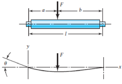
The designer of a shaft usually has a slope constraint imposed by the bearings used. This limit will be denoted as ξ. If the shaft shown in the figure is to have a uniform diameter d except in the locality of the bearing mounting, it can be approximated as a uniform beam with simple supports. Show that the minimum diameters to meet the slope constraints at the left and right bearings are, respectively,
Problem 4–45

Want to see the full answer?
Check out a sample textbook solution
Chapter 4 Solutions
Shigley's Mechanical Engineering Design (McGraw-Hill Series in Mechanical Engineering)
- : +0 usão العنوان on to A vertical true centrifugal casting process is used to produce bushings that are 250 mm long and 200 mm in outside diameter. If the rotational speed during solidification is 500 rev/min, determine the inside radii at the top and bottom of the bushing if R-2R. Take: -9.81 mis ۲/۱ ostrararrow_forward: +0 العنوان use only In conventional drawing of a stainless steel wire, the original diameter D.-3mm, the area reduction at each die stand r-40%, and the proposed final diameter D.-0.5mm, how many die stands are required to complete this process. онarrow_forwardIn non-continuous dieless drawing process for copper tube as shown in Fig. (1), take the following data: Do-20mm, to=3mm, D=12mm, ti/to=0.6 and vo-15mm/s. Calculate: (1) area reduction RA, (2) drawing velocity v. Knowing that: t₁: final thickness D₁ V. Fig. (1) Darrow_forward
- A vertical true centrifugal casting process is used to produce bushings that are 250 mm long and 200 mm in outside diameter. If the rotational speed during solidification is 500 rev/min, determine the inside radii at the top and bottom of the bushing if R-2Rb. Take: 8-9.81 m/sarrow_forwardIn conventional drawing of a stainless steel wire, the original diameter D.-3mm, the area reduction at each die stand r-40%, and the proposed final diameter D₁-0.5mm, how many die stands are required to complete this process.arrow_forwardA vertical true centrifugal casting process is used to produce bushings that are 250 mm long and 200 mm in outside diameter. If the rotational speed during solidification is 500 rev/min, determine the inside radii at the top and bottom of the bushing if R-2Rb. Take: 8-9.81 m/sarrow_forward
- In non-continuous dieless drawing process for copper tube as shown in Fig. (1), take the following data: Do-20mm, to=3mm, D=12mm, ti/to=0.6 and vo-15mm/s. Calculate: (1) area reduction RA, (2) drawing velocity v. Knowing that: t₁: final thickness D₁ V. Fig. (1) Darrow_forward-6- 8 من 8 Mechanical vibration HW-prob-1 lecture 8 By: Lecturer Mohammed O. attea The 8-lb body is released from rest a distance xo to the right of the equilibrium position. Determine the displacement x as a function of time t, where t = 0 is the time of release. c=2.5 lb-sec/ft wwwww k-3 lb/in. 8 lb Prob. -2 Find the value of (c) if the system is critically damping. Prob-3 Find Meq and Ceq at point B, Drive eq. of motion for the system below. Ш H -7~ + 目 T T & T тт +arrow_forwardQ For the following plan of building foundation, Determine immediate settlement at points (A) and (B) knowing that: E,-25MPa, u=0.3, Depth of foundation (D) =1m, Depth of layer below base level of foundation (H)=10m. 3m 2m 100kPa A 2m 150kPa 5m 200kPa Barrow_forward
- W PE 2 43 R² 80 + 10 + kr³ Ø8=0 +0 R²+J+ kr200 R² + J-) + k r² = 0 kr20 kr20 8+ W₁ = = 0 R²+1) R²+J+) 4 lec 8.pdf Mechanical vibration lecture 6 By: Lecturer Mohammed C. Attea HW1 (Energy method) Find equation of motion and natural frequency for the system shown in fig. by energy method. m. Jo 000 HW2// For the system Fig below find 1-F.B.D 2Eq.of motion 8 wn 4-0 (1) -5- marrow_forwardThe hose supplying the cylinder operating the bucket of a large excavator has fluid at 1000 psi flowing at 5 gpm. What is theavailable power in the line?arrow_forwardQ For the following plan of building foundation, Determine immediate settlement at points (A) and (B) knowing that: E,-25MPa, u=0.3, Depth of foundation (D) =1m, Depth of layer below base level of foundation (H)=10m. 3m 2m 100kPa A 2m 150kPa 5m 200kPa Barrow_forward
 Elements Of ElectromagneticsMechanical EngineeringISBN:9780190698614Author:Sadiku, Matthew N. O.Publisher:Oxford University Press
 Mechanics of Materials (10th Edition)Mechanical EngineeringISBN:9780134319650Author:Russell C. HibbelerPublisher:PEARSON
 Thermodynamics: An Engineering ApproachMechanical EngineeringISBN:9781259822674Author:Yunus A. Cengel Dr., Michael A. BolesPublisher:McGraw-Hill Education
 Control Systems EngineeringMechanical EngineeringISBN:9781118170519Author:Norman S. NisePublisher:WILEY
 Mechanics of Materials (MindTap Course List)Mechanical EngineeringISBN:9781337093347Author:Barry J. Goodno, James M. GerePublisher:Cengage Learning
 Engineering Mechanics: StaticsMechanical EngineeringISBN:9781118807330Author:James L. Meriam, L. G. Kraige, J. N. BoltonPublisher:WILEY


