
Concept explainers
Videos
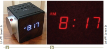
You are working for an electronics company that makes devices for the home. Your supervisor has given you an assignment to help design the projection mechanism for a projection alarm clock. In this type of clock, a projection system is mounted on the body of the clock, as shown in Figure P35.31a, where the projection system is the silver cylinder, of radius R = 3.25 cm, mounted on the left side of the clock. A converging lens is mounted on the edge of the cylinder. Inside the cylinder, a small digital display of the time in red characters can be moved from the center of the cylinder outward radially toward the lens. The red light of the digital display can he seen in the lens in Figure P35.31a. As a result, an image of the time is projected in red onto the ceiling or wall of a darkened room (Fig. P35.31b). The range of distances for focused images of the digital display is from 0.500 m to 4.00 m, measured from the center of the cylinder. For the smallest value of the range, the digital display is at the center of the cylinder. You must determine for your supervisor the following parameters for the design of the projection system: (a) the focal length of the lens and (b) the distance of the digital display from the center of the cylinder for the largest value of the range.
Figure P35.31
Want to see the full answer?
Check out a sample textbook solution
Chapter 35 Solutions
Physics for Scientists and Engineers


- Two converging lenses having focal lengths of f1 = 10.0 cm and f2 = 20.0 cm are placed a distance d = 50.0 cm apart as shown in Figure P35.48. The image due to light passing through both lenses is to be located between the lenses at the position x = 31.0 cm indicated. (a) At what value of p should the object be positioned to the left of the first lens? (b) What is the magnification of the final image? (c) Is the final image upright or inverted? (d) Is the final image real or virtual?arrow_forwardWhy is the following situation impossible? Consider the lensmirror combination shown in Figure P35.55. The lens has a focal length of fL = 0.200 m, and the mirror has a focal length of fM = 0.500 m. The lens and mirror are placed a distance d = 1.30 m apart, and an object is placed at p = 0.300 m from the lens. By moving a screen to various positions to the left of the lens, a student finds two different positions of the screen that produce a sharp image of the object. One of these positions corresponds to light leaving the object and traveling to the left through the lens. The other position corresponds to light traveling to the right from the object, reflecting from the mirror and then passing through the lens. Figure P35.55 Problem 55 and 57.arrow_forwardFigure P38.76 shows an object placed a distance do1 from one of two converging lenses separated by s = 1.00 m. The first lens has focal length f1 = 22.0 cm, and the second lens has focal length f2 = 45.0 cm. An image is formed by light passing through both lenses at a distance di2 = 15.0 cm to the left of the second lens. a. What is the value of do1 that will result in this image position? b. Is the final image formed by the two lenses real or virtual? c. What is the magnification of the final image? d. Is the final image upright or inverted? Figure P38.76arrow_forward
- Figure P38.43 shows a concave meniscus lens. If |r1| = 8.50 cm and |r2| = 6.50 cm, find the focal length and determine whether the lens is converging or diverging. The lens is made of glass with index of refraction n = 1.55. CHECK and THINK: How do your answers change if the object is placed on the right side of the lens? FIGURE P38.43arrow_forwardA diverging lens located in the y-z plane at x = 0 forms an image of an arrow at x = x2 = -22.7 cm. The image of the tip of the arrow is located at y = y2 = 3.8 cm. The magnitude of the focal length of the diverging lens is 46.3 cm. What is y1, the y-coordinate of the tip of the object arrow? A converging lens of focal length fconverging = 15.44 cm is now inserted at x = x3 = -23.16 cm. In the absence of the diverging lens, at what x co-ordinate, x4, would the image of the arrow form? To determine the image of the arrow from the combined converging + diverging lens system, we take the image from the converging lens (in the absence of the diverging lens) to be the object for the diverging lens. If this image is downstream of the diverging lens, the object for the diverging lens is virtual. All this means is that the rays entering the diverging lens are converging towards a location downstream of the diverging lens. The final image can be calculated using this virtual object distance and…arrow_forward
 Physics for Scientists and Engineers with Modern ...PhysicsISBN:9781337553292Author:Raymond A. Serway, John W. JewettPublisher:Cengage Learning
 Physics for Scientists and EngineersPhysicsISBN:9781337553278Author:Raymond A. Serway, John W. JewettPublisher:Cengage Learning
 Physics for Scientists and Engineers: Foundations...PhysicsISBN:9781133939146Author:Katz, Debora M.Publisher:Cengage Learning