Concept explainers
The equivalent inductance for the system.
Answer to Problem 83CP
The equivalent inductance for the system is
Explanation of Solution
The flow of current in the circuit is as shown in the figure below.
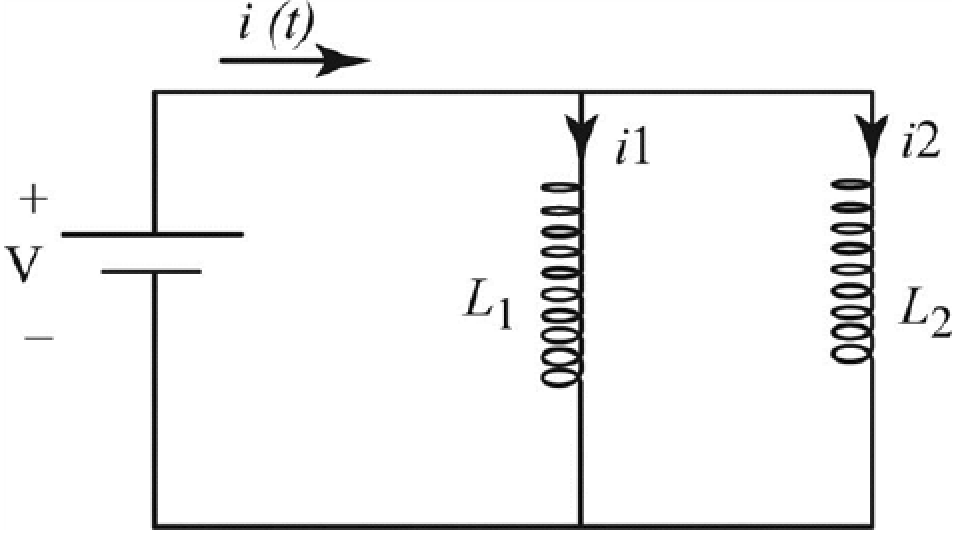
Figure-(1)
Here,
Write the expression based on junction rule.
Here,
Write the expression to obtain the loop rule.
Here,
Write the expression based on junction rule to obtain the current division in the circuit.
Here,
Differentiate the above equation with respect to time
Write the expression based on loop rule to obtain the potential drop in the left loop.
Write the expression based on loop rule to obtain the potential drop in the right loop.
As the inductor
Compare equation (III) and (IV).
Further solve the above equation.
Substitute
Write the expression to obtain the voltage across the circuit.
Here,
Substitute
Further substitute
Compare equation (V) and (VI).
Further solve the above equation.
Therefore, the equivalent inductance for the system is
Want to see more full solutions like this?
Chapter 32 Solutions
Physics for Scientists and Engineers with Modern, Revised Hybrid (with Enhanced WebAssign Printed Access Card for Physics, Multi-Term Courses)


- When a wire carries an AC current with a known frequency, you can use a Rogowski coil to determine the amplitude Imax of the current without disconnecting the wire to shunt the current through a meter. The Rogowski coil, shown in Figure P23.8, simply clips around the wire. It consists of a toroidal conductor wrapped around a circular return cord. Let n represent the number of turns in the toroid per unit distance along it. Let A represent the cross-sectional area of the toroid. Let I(t) = Imax sin t represent the current to be measured. (a) Show that the amplitude of the emf induced in the Rogowski coil is Emax=0nAImax. (b) Explain why the wire carrying the unknown current need not be at the center of the Rogowski coil and why the coil will not respond to nearby currents that it does not enclose. Figure P23.8arrow_forwardOne application of an RL circuit is the generation of lime-varying high voltage from a low-volt age source as shown in Figure P32.82. (a) What is the current in the circuit a long time after the switch has been in position a? (b) Now the switch is thrown quickly from a to b. Compute the initial voltage across each resistor and across the inductor. (c) How much time elapses before the voltage across the inductor drops to 12.0 Y?arrow_forwardTwo coaxial cables of length with radii a and b are carrying currents in opposite directions as shown in Figure P33.78. Determine the inductance of the system. Hint: Use Ampres law to write an expression for the magnetic field in the region between the cables, a distance r from the axis of the cables. Then calculate the magnetic flux through a narrow rectangular region between the cables such that the Field is perpendicular to the area everywhere. FIGURE P33.78arrow_forward
 Physics for Scientists and EngineersPhysicsISBN:9781337553278Author:Raymond A. Serway, John W. JewettPublisher:Cengage Learning
 Physics for Scientists and Engineers with Modern ...PhysicsISBN:9781337553292Author:Raymond A. Serway, John W. JewettPublisher:Cengage Learning
 Physics for Scientists and Engineers: Foundations...PhysicsISBN:9781133939146Author:Katz, Debora M.Publisher:Cengage Learning
 Principles of Physics: A Calculus-Based TextPhysicsISBN:9781133104261Author:Raymond A. Serway, John W. JewettPublisher:Cengage Learning
 Physics for Scientists and Engineers, Technology ...PhysicsISBN:9781305116399Author:Raymond A. Serway, John W. JewettPublisher:Cengage Learning