Concept explainers
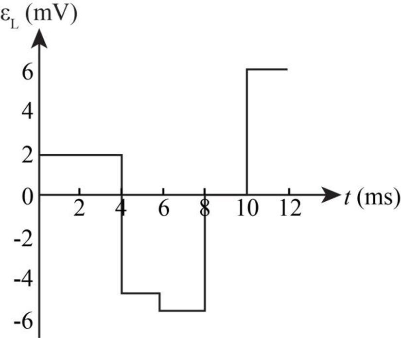
The graph for the self induced emf over the given time interval.
Answer to Problem 14P
The graph for the self induced emf over the given time interval is shown below.
Explanation of Solution
Write the expression to calculate the self induced emf.
Here,
Write the expression to for change in current.
Here,
Substitute
Conclusion:
For the interval
Substitute
For the interval
Substitute
For the interval
Substitute
For the interval
Substitute
For the interval
Substitute
For the interval
Substitute
Therefore, the graph for the self inductance at different time interval is shown in the figure below.

Figure-(1)
Want to see more full solutions like this?
Chapter 32 Solutions
Physics for Scientists and Engineers with Modern, Revised Hybrid (with Enhanced WebAssign Printed Access Card for Physics, Multi-Term Courses)


- The current I(t) through a 5.0-mH inductor varies with time, as shown below. The resistance of the inductor is 5.0 . Calculate the voltage across the inductor at t = 2.0 ms, r = 4.0 ms, and t = 8.0 ms.arrow_forwardConsider the circuit in Figure P32.18, taking = 6.00 V, L = 8.00 mH, and R = 4.00 . (a) What is the inductive time constant of the circuit? (b) Calculate the current in the circuit 250 s after the switch is closed. (c) What is the value of the final steady-state current? (d) After what time interval does the current reach 80.0% of its maximum value?arrow_forwardIn the transformer shown in Figure P33.51, the load resistance RL is 50.0 . The turns ratio N1/N2 is 2.50, anti the rms source voltage is Vs = 80.0 V. If a voltmeter across the load resistance measures an rms voltage of 25.0 V, what is the source resistance Rs?arrow_forward
- When a wire carries an AC current with a known frequency, you can use a Rogowski coil to determine the amplitude Imax of the current without disconnecting the wire to shunt the current through a meter. The Rogowski coil, shown in Figure P23.8, simply clips around the wire. It consists of a toroidal conductor wrapped around a circular return cord. Let n represent the number of turns in the toroid per unit distance along it. Let A represent the cross-sectional area of the toroid. Let I(t) = Imax sin t represent the current to be measured. (a) Show that the amplitude of the emf induced in the Rogowski coil is Emax=0nAImax. (b) Explain why the wire carrying the unknown current need not be at the center of the Rogowski coil and why the coil will not respond to nearby currents that it does not enclose. Figure P23.8arrow_forwardA 75-turn, 10.0 cm diameter coil rotates at an angular velocity of 8.00 radius in a 1.25 T field, starting with the plane of the coil parallel to the field. (a) What is the peak emf? (b) At what time is the peak emf first reached? (c) At what time is the emf first at its meet negative? (d) What is the period of the AC voltage output?arrow_forward
 Physics for Scientists and Engineers with Modern ...PhysicsISBN:9781337553292Author:Raymond A. Serway, John W. JewettPublisher:Cengage Learning
 Physics for Scientists and EngineersPhysicsISBN:9781337553278Author:Raymond A. Serway, John W. JewettPublisher:Cengage Learning
 Principles of Physics: A Calculus-Based TextPhysicsISBN:9781133104261Author:Raymond A. Serway, John W. JewettPublisher:Cengage Learning
 Physics for Scientists and Engineers: Foundations...PhysicsISBN:9781133939146Author:Katz, Debora M.Publisher:Cengage Learning
 Physics for Scientists and Engineers, Technology ...PhysicsISBN:9781305116399Author:Raymond A. Serway, John W. JewettPublisher:Cengage Learning