
Videos
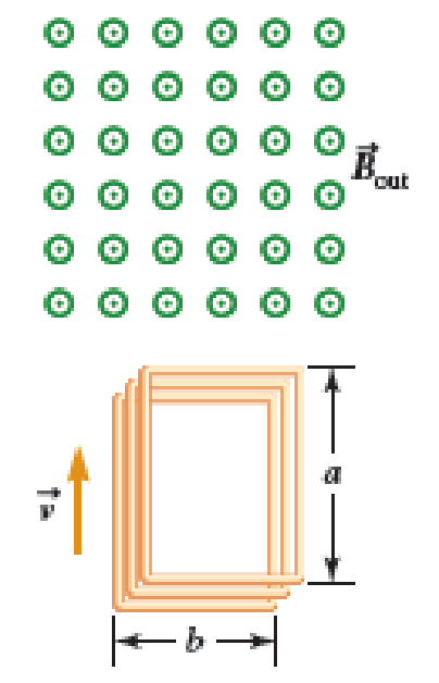
A Figure P32.74 shows an N-turn rectangular coil of length a and width b entering a region of uniform magnetic field of magnitude Bout directed out of the page. The velocity of the coil is constant and is upward in the figure. The total resistance of the coil is R. What are the magnitude and direction of the magnetic force on the coil a. when only a portion of the coil has entered the region with the field, b. when the coil is completely embedded in the field, and c. as the coil begins to exit the region with the field?
(a)
The magnitude and direction of the magnetic force on the coil when a portion of the coil enters the region of the field.
Answer to Problem 74PQ
The magnitude of the magnetic force on the coil when a portion of the coil enters the region of the field is
Explanation of Solution
Faraday’s law states that an emf is induced in a coil when the magnetic flux linked with the coil changes.
The direction of the induced emf is given by Lenz law. Lenz law states that the current induced in a circuit due to change or a motion in the magnetic field, opposes the change in flux and exerts a mechanical force opposing the motion.
A current carrying conductor experiences a force in a magnetic field. Thus, the conductor experiences a force due to the current induced in it.
A coil ABCD of
The coil moves with a constant velocity
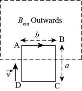
Figure-(1)
Write the expression for the induced emf entering the magnetic field.
Write the expression for magnitude of the induced current in the coil.
Here,
Substitute equation (I) in the above equation to find
The flux entering the coil increases, as the coil enters the magnetic field. According to Lenz law, the current in the segment which enters the field, flows towards the right, from point A to point B.
Write the expression for force experienced by the segment due to current flowing in the coil.
According to the right hand screw rule, the force acts perpendicular to both the direction of current and the magnetic field. Therefore, the force acts downwards.
Write the expression for magnitude of the force.
Substitute equation (II) in the above equation to find
Conclusion:
Therefore, the magnitude of the magnetic force on the coil, when a portion of the coil enters the region of the field is
(b)
The magnitude and direction of the magnetic force on the coil when the coil is completely embedded in the field.
Answer to Problem 74PQ
The magnitude of the force on the coil when it is completely embedded in the magnetic field is
Explanation of Solution
As shown in Figure-(2), the coil is completely embedded in the field.
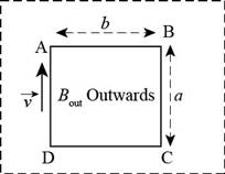
Figure-(2)
According to Faraday’s law of electromagnetic induction, the emf induced in the coil is
There is no current flow in the coil, when the induced emf is
Conclusion:
Therefore, the magnetic force on the coil when it is completely embedded in the magnetic field is
(c)
The magnitude and direction of the magnetic force on the coil as the coil begins to exit the region of the field.
Answer to Problem 74PQ
The magnitude of the magnetic force on the coil, when a portion of the coil exits the region of the field is
Explanation of Solution
The outward flux through the coil decreases, as the coil begins to exit the field. The current flows in the counter clockwise direction in the coil. The current flows from point D to point C as shown in figure-(3).
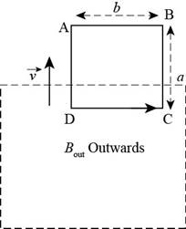
Figure-(3)
The magnitude of the current in the coil remains the same as it is when the coil enters the field, as the coil moves with the same constant speed. The direction of the current flowing in the coil, when it exits the field, is opposite to the direction of the current when the coil enters the field.
Write the expression for the current in the coil when it exits the magnetic field.
Write the expression for magnitude of the force experienced by the coil.
The magnitude of the force experienced by the coil, when it exits the field is same as, when it enters the field.
The force acts downwards along the plane of the paper.
Conclusion:
Therefore, the magnitude of the magnetic force on the coil, when a portion of the coil exits the region of the field is
Want to see more full solutions like this?
Chapter 32 Solutions
Physics for Scientists and Engineers: Foundations and Connections


- Figure P32.21 shows a circular conducting loop with a 5.00-cm radius and a total resistance of 1.30 placed within a uniform magnetic field pointing into the page. a. What is the rate at which the magnetic field is changing if a counterclockwise current I = 4.60 102 A is induced in the loop? b. Is the induced current caused by an increase or a decrease in the magnetic field with time?arrow_forwardA metal rod of mass M and length L is pivoted about a hinge at point O as shown in Figure P32.80. The axis of rotation passes through O into the page. A constant magnetic field B is applied into the page. Find the ratio of the maximum electric field inside the rod to the applied magnetic field when the rod is rotated with angular speed . Assume the speed of the rod is determined by the linear speed of its center of mass, and its mass is uniformly distributed. FIGURE P32.80arrow_forwardA piece of insulated wire is shaped into a figure eight as shown in Figure P23.12. For simplicity, model the two halves of the figure eight as circles. The radius of the upper circle is 5.00 cm and that of the lower circle is 9.00 cm. The wire has a uniform resistance per unit length of 3.00 Ω/m. A uniform magnetic field is applied perpendicular to the plane of the two circles, in the direction shown. The magnetic field is increasing at a constant rate of 2.00 T/s. Find (a) the magnitude and (b) the direction of the induced current in the wire. Figure P23.12arrow_forward
- A loop of wire in the shape of a rectangle of width w and length L and a long, straight wire carrying a current I lie on a tabletop as shown in Figure P23.7. (a) Determine the magnetic flux through the loop due to the current I. (b) Suppose the current is changing with time according to I = a + bt, where a and b are constants. Determine the emf that is induced in the loop if b = 10.0 A/s, h = 1.00 cm, w = 10.0 cm, and L = 1.00 m. (c) What is the direction of the induced current in the rectangle? Figure P23.7arrow_forwardA toroid has a major radius R and a minor radius r and is tightly wound with N turns of wire on a hollow cardboard torus. Figure P31.6 shows half of this toroid, allowing us to see its cross section. If R r, the magnetic field in the region enclosed by the wire is essentially the same as the magnetic field of a solenoid that has been bent into a large circle of radius R. Modeling the field as the uniform field of a long solenoid, show that the inductance of such a toroid is approximately L=120N2r2R Figure P31.6arrow_forwardA current-carrying conductor PQ of mass m and length L is placed on an inclined plane with angle of inclination (Fig. P30.93). A uniform magnetic field B is directed upward as shown. Assume friction is negligible. a. Determine the magnitude and direction of the current in the conductor so that it remains in equilibrium. b. If the direction of the current is reversed, will the conductor still be in equilibrium? If not, find the magnitude of the initial acceleration of the conductor. FIGURE P30.93arrow_forward
- A circular coil 15.0 cm in radius and composed of 145 tightly wound turns carries a current of 2.50 A in the counterclockwise direction, where the plane of the coil makes an angle of 15.0 with the y axis (Fig. P30.73). The coil is free to rotate about the z axis and is placed in a region with a uniform magnetic field given by B=1.35jT. a. What is the magnitude of the magnetic torque on the coil? b. In what direction will the coil rotate? FIGURE P30.73arrow_forwardA rectangular coil with resistance R has N turns, each of length and width as shown in Figure P31.36. The coil moves into a uniform magnetic field B with constant velocity v. What are the magnitude and direction of the total magnetic force on the coil (a) as it enters the magnetic field, (b) as it moves within the field, and (c) as it leaves the field?arrow_forwardFor both sketches in Figure P30.56, there is a 3.54-A current, a magnetic field strength B 0.650 T. and the angle is 32.0. Find the magnetic force per unit length (magnitude and direction) exerted on the current-carrying conductor in both cases.arrow_forward
- A constant magnetic field of 0.275 T points through a circular loop of wire with radius 3.50 cm as shown in Figure P32.1. a. What is the magnetic flux through the loop? b. Is a current induced in the loop? Explain. FIGURE P32.1arrow_forwardA uniform magnetic field B=5.44104iT passes through a closed surface with a slanted top as shown in Figure P31.59. a. Given the dimensions and orientation of the closed surface shown, what is the magnetic flux through the slanted top of the surface? b. What is the net magnetic flux through the entire closed surface?arrow_forward
 Physics for Scientists and Engineers: Foundations...PhysicsISBN:9781133939146Author:Katz, Debora M.Publisher:Cengage Learning
 Physics for Scientists and Engineers, Technology ...PhysicsISBN:9781305116399Author:Raymond A. Serway, John W. JewettPublisher:Cengage Learning
 Principles of Physics: A Calculus-Based TextPhysicsISBN:9781133104261Author:Raymond A. Serway, John W. JewettPublisher:Cengage Learning
 Physics for Scientists and Engineers with Modern ...PhysicsISBN:9781337553292Author:Raymond A. Serway, John W. JewettPublisher:Cengage Learning
 Physics for Scientists and EngineersPhysicsISBN:9781337553278Author:Raymond A. Serway, John W. JewettPublisher:Cengage Learning