
Fundamentals of Electric Circuits
6th Edition
ISBN: 9780078028229
Author: Charles K Alexander, Matthew Sadiku
Publisher: McGraw-Hill Education
expand_more
expand_more
format_list_bulleted
Concept explainers
Videos
Textbook Question
Chapter 3.2, Problem 2PP
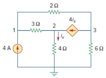
Figure 3.6
For Practice Prob. 3.2.
Find the voltages at the three nonreference nodes in the circuit of Fig. 3.6.
Answer: v1 = 32 V, v2 = −25.6 V, v3 = 62.4 V.
Expert Solution & Answer
Want to see the full answer?
Check out a sample textbook solution
Students have asked these similar questions
mponent of nódal
ch element. There is no way of knowing the current through
wever, KCL must be satisfied at a sunernode like any other node. Hence a tde
spernode in Fig. 3.5,
i + i4 = i2 + i3
(3.11a)
v1 - v2
v1 - v3
v2 – 0
v3 - 0
(3.11b)
6.
To apply Kirchhoff's voltage law to the supernode in Fig. 3.4 we redraw the circuit as
shown in Fig. 3.5. Going around the loop in the clockwise»direction gives
-V2 + 5 + v3 = 0=v2 – V3 = 5
(3.12)
From Eqs. (3.10), (3.11b), and (3.12), we obtain the node volltages.
5V
د مُسق ک من ؤ
Figure 3.5 Applying KVL to a supernode.
Example 3.2: For the circuit shown in Fig. 3.6, find the node voltages.
Solution:
The supernode contains the 2-V source, nodes 1 and
10 2
www
2, and the 10-2 resistor. Applying KCL to the
2 V
supernode as shown in Fig. 3.7(a) gives
2.
12
2 = i + iz +7
7 A
Expressing in and iz in terms of the node voltages
2 A
22
v1 - 0
v2 - 0
2 =
7
4
or
(3.2.1)
V2 =-20 - 2vVI
Figure 3.6 For Example 3.2.
ESTHRER: ALI SHARAAN
METHORS OF ANALYSIS…
Q3) For the network shown in the figure below, determine the following:
a) fe b) Zinl and Zin2
c) Zo1 and Zo2
d) Avı, Av2, and AVT
+20 V
6.8 kQ
30 ka
6.8 ka
30 ka
0.5 F
0.5 uF
P-150
B- 150
1.5 ka
50 uF
1.5 ka
50 uF
Network
2R
R
3V
2R
-1.5 mA
A network is implemented with three resistors and a voltage source as shown above.
Its terminal characteristics are also given graphically above.
From the graphical data given above, determine Thevenin equivalent voltage in volts
for the network.
Your Answer:
Answer
Chapter 3 Solutions
Fundamentals of Electric Circuits
Ch. 3.2 - Figure 3.4 For Practice Prob. 3.1. Obtain the node...Ch. 3.2 - Figure 3.6 For Practice Prob. 3.2. Find the...Ch. 3.3 - Figure 3.11 For Practice Prob. 3.3. Find v and i...Ch. 3.3 - Figure 3.14 For Practice Prob. 3.4. Find v1, v2,...Ch. 3.4 - Practice Problem 3.5 Figure 3.19 For Practice...Ch. 3.4 - Practice Problem 3.6 Figure 3.21 For Practice...Ch. 3.5 - Practice Problem 3.7 Figure 3.25 For Practice...Ch. 3.6 - By inspection, obtain the node-voltage equations...Ch. 3.6 - By inspection, obtain the mesh-current equations...Ch. 3.8 - For the circuit in Fig. 3.33, use PSpice to find...
Ch. 3.8 - Use PSpice to determine currents i1, i2, and i3 in...Ch. 3.9 - For the transistor circuit in Fig. 3.42, let =...Ch. 3.9 - The transistor circuit in Fig. 3.45 has = 80 and...Ch. 3 - At node 1 in the circuit of Fig. 3.46, applying...Ch. 3 - Figure 3.46 For Review Questions 3.1 and 3.2 In...Ch. 3 - For the circuit in Fig. 3.47, v1 and v2 are...Ch. 3 - Figure 3.47 For Review Questions 3.3 and 3.4....Ch. 3 - The circuit i in the circuit of Fig. 3.48 is:...Ch. 3 - Figure 3.48 For Review Questions 3.5 and 3.6....Ch. 3 - In the circuit of Fig. 3.49, current i1 is: (a)4 A...Ch. 3 - Figure 3.49 For Review Questions 3.7 and 3.8....Ch. 3 - The PSpice part name for a current-controlled...Ch. 3 - Which of the following statements are not true of...Ch. 3 - Using Fig. 3.50, design a problem to help other...Ch. 3 - For the circuit in Fig. 3.51, obtain v1 and v2....Ch. 3 - Find the currents I1 through I4 and the voltage vo...Ch. 3 - Given the circuit in Fig. 3.53, calculate the...Ch. 3 - Obtain vo in the circuit of Fig. 3.54. Figure 3.54...Ch. 3 - Solve for V1 in the circuit of Fig. 3.55 using...Ch. 3 - Apply nodal analysis to solve for Vx in the...Ch. 3 - Using nodal analysis, find vo in the circuit of...Ch. 3 - Determine Ib in the circuit in Fig. 3.58 using...Ch. 3 - Prob. 10PCh. 3 - Find Vo and the power dissipated in all the...Ch. 3 - Using nodal analysis, determine Vo in the circuit...Ch. 3 - Calculate v1 and v2 in the circuit of Fig. 3.62...Ch. 3 - Using nodal analysis, find vo in the circuit of...Ch. 3 - Apply nodal analysis to find io and the power...Ch. 3 - Determine voltages v1 through v3 in the circuit of...Ch. 3 - Prob. 17PCh. 3 - Determine the node voltages in the circuit in Fig....Ch. 3 - Use nodal analysis to find v1, v2 and v3 in the...Ch. 3 - For the circuit in Fig. 3.69, find v1, v2, and v3...Ch. 3 - For the circuit in Fig. 3.70, find v1 and v2 using...Ch. 3 - Determine v1 and v2 in the circuit of Fig. 3.71....Ch. 3 - Use nodal analysis to find Vo in the circuit of...Ch. 3 - Use nodal analysis and MATLAB to find Vo in the...Ch. 3 - Use nodal analysis along with MATLAB to determine...Ch. 3 - Calculate the node voltages v1, v2, and v3 in the...Ch. 3 - Use nodal analysis to determine voltages v1, v2,...Ch. 3 - Use MATLAB to find the voltages at nodes a, b, c,...Ch. 3 - Use MATLAB to solve for the node voltages in the...Ch. 3 - Using nodal analysis, find vo and io in the...Ch. 3 - Find the node voltages for the circuit in Fig....Ch. 3 - Obtain the node voltages v1, v2, and v3 in the...Ch. 3 - Which of the circuits in Fig. 3.82 is planar? For...Ch. 3 - Determine which of the circuits in Fig. 3.83 is...Ch. 3 - Figure 3.54 For Prob. 3.5. Rework Prob. 3.5 using...Ch. 3 - Use mesh analysis to obtain ia, ib, and ic in the...Ch. 3 - Using nodal analysis, find vo in the circuit of...Ch. 3 - Apply mesh analysis to the circuit in Fig. 3.85...Ch. 3 - Using Fig. 3.50 from Prob. 3.1, design a problem...Ch. 3 - Prob. 40PCh. 3 - Apply mesh analysis to find i in Fig. 3.87. Figure...Ch. 3 - Using Fig. 3.88, design a problem to help students...Ch. 3 - Prob. 43PCh. 3 - Prob. 44PCh. 3 - Prob. 45PCh. 3 - Calculate the mesh currents i1 and i2 in Fig....Ch. 3 - Rework Prob. 3.19 using mesh analysis. Use nodal...Ch. 3 - Prob. 48PCh. 3 - Find vo and io in the circuit of Fig. 3.94. Figure...Ch. 3 - Prob. 50PCh. 3 - Apply mesh analysis to find vo in the circuit of...Ch. 3 - Use mesh analysis to find i1, i2 and i3 in the...Ch. 3 - Prob. 53PCh. 3 - Find the mesh currents i1, i2, and i3 in the...Ch. 3 - In the circuit of Fig. 3.100, solve for I1, I2,...Ch. 3 - Determine v1 and v2 in the circuit of Fig. 3.101....Ch. 3 - In the circuit of Fig. 3.102, find the values of...Ch. 3 - Find i1, i2, and i3 in the circuit of Fig. 3.103....Ch. 3 - Rework Prob. 3.30 using mesh analysis. Using nodal...Ch. 3 - Prob. 60PCh. 3 - Calculate the current gain iois in the circuit of...Ch. 3 - Find the mesh currents i1, i2, and i3 in the...Ch. 3 - Find vx and ix in the circuit shown in Fig. 3.107....Ch. 3 - Find vo and io in the circuit of Fig. 3.108.Ch. 3 - Use MATLAB to solve for the mesh currents in the...Ch. 3 - Write a set of mesh equations for the circuit in...Ch. 3 - Obtain the node-voltage equations for the circuit...Ch. 3 - Prob. 68PCh. 3 - For the circuit shown in Fig. 3.113, write the...Ch. 3 - Write the node-voltage equations by inspection and...Ch. 3 - Write the mesh-current equations for the circuit...Ch. 3 - Prob. 72PCh. 3 - Write the mesh-current equations for the circuit...Ch. 3 - By inspection, obtain the mesh-current equations...Ch. 3 - Use PSpice or MultiSim to solve Prob. 3.58....Ch. 3 - Use PSpice or MultiSim to solve Prob. 3.27....Ch. 3 - Solve for V1 and V2 in the circuit of Fig. 3.119...Ch. 3 - Solve Prob. 3.20 using PSpice or MultiSim. 3.20...Ch. 3 - Prob. 79PCh. 3 - Find the nodal voltages v1 through v4 in the...Ch. 3 - Use PSpice or MultiSim to solve the problem in...Ch. 3 - If the Schematics Netlist for a network is as...Ch. 3 - The following program is the Schematics Netlist of...Ch. 3 - Prob. 84PCh. 3 - An audio amplifier with a resistance of 9 ...Ch. 3 - Prob. 86PCh. 3 - For the circuit in Fig. 3.123, find the gain...Ch. 3 - Determine the gain vo/vs of the transistor...Ch. 3 - For the transistor circuit shown in Fig. 3.125,...Ch. 3 - Calculate vs for the transistor in Fig. 3.126...Ch. 3 - Prob. 91PCh. 3 - Prob. 92PCh. 3 - Rework Example 3.11 with hand calculation. In the...
Knowledge Booster


Learn more about
Need a deep-dive on the concept behind this application? Look no further. Learn more about this topic, electrical-engineering and related others by exploring similar questions and additional content below.Similar questions
- Practice problem 3.2: Find v and i in the eircuit in Figure below. Answer: -0.2 V, 1.4 A. 3 V mediča 7Varrow_forwardPractice problem 3.2: Find v and i in the eircuit in Figure below. Answer: -0.2 V, 1.4 A. 3 V ww i 7 V ww omedičearrow_forward3. Research on the Thevenin's and Norton's theorem and their relations. Write those findings. 4. Derive the equation for VTH for circuit in Figure 3. 5. Derive the equation for RTH for circuit in Figure 3. 6. Derive the equation for IN for circuit in Figure 3. R6 m A 220 ohms R1 V1 R4 m 820 ohms 330 ohms 10 V R2 V2 560 ohms B R5 m vo 1 kohms 470 ohms 5 V FIGURE 3 R3arrow_forward
- Refer to the figure. Given 2RRL² R2 = 3R2 – R_° a) Design the power supply cireuit so that vị = 3v,when R1 = 600 2. b) Assume input voltage is 180 V. Which resistor in the circuit dissipates the most power? What is the power? c) Which resistor dissipates the least power? What is the power? R: ww- R R ww + Vi R Vo RL b d wwarrow_forward8V For the network of Figure Q3, determine: a) Ir b) Ve c) Vr 2.2 k2 1.8 ka +10Varrow_forwardQ.3 Determine V, for the following figure, where V1=V2=1v. R2 R6 6kQ 20kQ R1 V1. R3 N 2ka 741 10ka 741 Vout R5 R4 20kQ 6kQ R7 1kQ 741 V2 •arrow_forward
- Q3) For the network shown in the figure below, determine the following: a) re b) Zini and Zinz c) Zoj and Zo2 d) Av1, Av2, and AvT +20 V 6.8 ka 30 kQ 6.8 ka 30 ka 0.5 pF 0.5 uF 1150 B-150 1.5 ka 50 uF 1.5 ka 50 uFarrow_forwardFor the given figure below, answer the following. 1. Resistor values in ohms.2. Use nodal analysis to determine V1, V2, and V3.3. Use mesh analysis to determine IS and Ix.arrow_forwardQ.3 Determine V. for the following figure, where V1=V2=1v. R2 R6 6kQ 20ka R1 V1 W R3 2kQ 741 10kQ 741 Vout R5 R4 20ko 6kQ R7 1ka 741 V2 •arrow_forward
- R. Vi (i VL In the circuit pictured, R1 = 8090N R2 = 550N R3 = 1820N R, = 40002 Vị = 84.5V 4 = 0.0084 A Use Thevenin's theorem to calculate, a.) Vin b.) Rth c.) the voltage across Rth d.) VI, e.) If you could replace R1 with any resistance value, calculate the value you would choose to deliver maximum power to the R1.arrow_forwardThe network N₁ shown below in Figure 3(a) contains a VCVS and is driven by an in- dependent current source. Using the values shown on the schematic, obtain the Nor- ton's equivalent network at terminals A-B of N₁ as shown in Figure 3(b). Label each component of the equivalent with its correct value. Show your work and explain in detail all assumptions you make. Jg₁ 20mA N₁ JN R3 R₁. 5KQ R₂ www 6ΚΩ + 3ΚΩ R4 7KQ V₂ (a) GN (b) μV4 B Figure 3 (a) Resistive network N₁ (b) Norton equivalent network (μ = 4V/V) Barrow_forward1) For the network shown in the below figure, the value of current needs to be measured in the 10002 by connecting a 502 ammeter between two terminals A and B, find the following: a) The actual value of current. b) The measured value of current. c) The percentage error in measurement. d) The accuracy of measurement. e) Repeat the aboveif a 25002 ammeter is connected between two terminals A and B. f) State your condlusion. ww 2000 n ww 1000 A Ammeter 500 5V 20002arrow_forward
arrow_back_ios
SEE MORE QUESTIONS
arrow_forward_ios
Recommended textbooks for you
 Introductory Circuit Analysis (13th Edition)Electrical EngineeringISBN:9780133923605Author:Robert L. BoylestadPublisher:PEARSON
 Delmar's Standard Textbook Of ElectricityElectrical EngineeringISBN:9781337900348Author:Stephen L. HermanPublisher:Cengage Learning
 Programmable Logic ControllersElectrical EngineeringISBN:9780073373843Author:Frank D. PetruzellaPublisher:McGraw-Hill Education
 Fundamentals of Electric CircuitsElectrical EngineeringISBN:9780078028229Author:Charles K Alexander, Matthew SadikuPublisher:McGraw-Hill Education
 Electric Circuits. (11th Edition)Electrical EngineeringISBN:9780134746968Author:James W. Nilsson, Susan RiedelPublisher:PEARSON
 Engineering ElectromagneticsElectrical EngineeringISBN:9780078028151Author:Hayt, William H. (william Hart), Jr, BUCK, John A.Publisher:Mcgraw-hill Education,
Introductory Circuit Analysis (13th Edition)
Electrical Engineering
ISBN:9780133923605
Author:Robert L. Boylestad
Publisher:PEARSON
Delmar's Standard Textbook Of Electricity
Electrical Engineering
ISBN:9781337900348
Author:Stephen L. Herman
Publisher:Cengage Learning
Programmable Logic Controllers
Electrical Engineering
ISBN:9780073373843
Author:Frank D. Petruzella
Publisher:McGraw-Hill Education
Fundamentals of Electric Circuits
Electrical Engineering
ISBN:9780078028229
Author:Charles K Alexander, Matthew Sadiku
Publisher:McGraw-Hill Education
Electric Circuits. (11th Edition)
Electrical Engineering
ISBN:9780134746968
Author:James W. Nilsson, Susan Riedel
Publisher:PEARSON
Engineering Electromagnetics
Electrical Engineering
ISBN:9780078028151
Author:Hayt, William H. (william Hart), Jr, BUCK, John A.
Publisher:Mcgraw-hill Education,
Thevenin's Theorem; Author: Neso Academy;https://www.youtube.com/watch?v=veAFVTIpKyM;License: Standard YouTube License, CC-BY