
Concept explainers
Videos
For the transistor circuit shown in Fig. 3.125, find IB and VCE. Let β = 100, and VBE = 0.7 V.
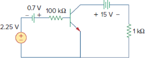
Figure 3.125
Find
Answer to Problem 89P
The value of
Explanation of Solution
Given data:
Refer Figure 3.125 in the textbook for the transistor circuit.
The common-emitter current gain
The base-emitter voltage
Formula used:
Write the expression for collector current in transistor.
Here,
Calculation:
Modify the given figure with the representation of currents and voltages as shown in Figure 1.
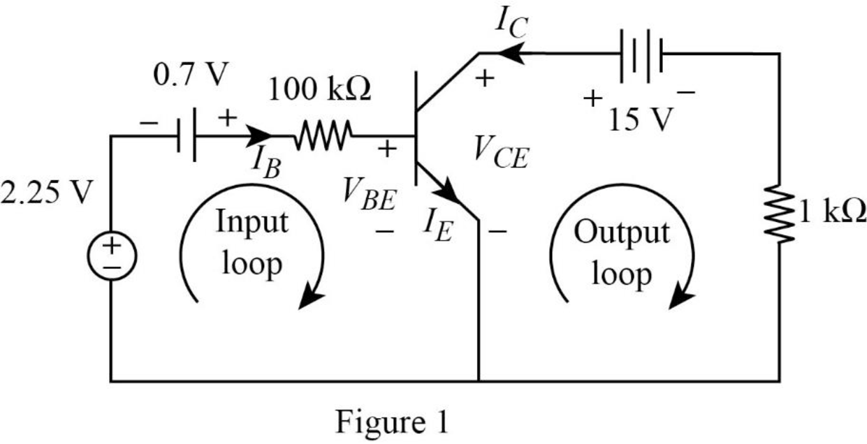
Apply Kirchhoff’s voltage law to input loop in Figure 1.
Substitute
Simplify the equation as follows.
Apply Kirchhoff’s voltage law to output loop in Figure 1.
Substitute equation (1) in (2).
Substitute
Conclusion:
Therefore, the value of
Want to see more full solutions like this?
Chapter 3 Solutions
Fundamentals of Electric Circuits


- A 80-W power transistor is to be cooled by attaching it to one of the commercially availableheat sinks. Select a heat sink that will allow the case temperature of the transistor not toexceed (70) °C in the ambient air at 30 °C. uses charts/table also if neededarrow_forwardexperiment (https://phet.colorado.edu/sims/html/circuit-construction-kit-dc-virtual-lab/latest/circuit-construction-kit-dc-virtual-lab_en.html):arrow_forwardSolve step by steo a) and b) please a) Determine Vs and Rs from a voltage source equivalent to a current source with Is = 500 mA and Rs = 600 Ω b) Determine Is and Rs of a current source equivalent to a voltage source with Vs = 13V and Rs = 10Ωarrow_forward
- draw the circuit diagram to implement the expression Abar BC(A+D whole bar)arrow_forwardWhich is the aspect ratio of the NMOS in the circuit to produce a drain current of 150 uA. 12.19 2.44 4.87 7.31arrow_forwardPlease show how you calculated Vth using node voltage analysis or mesh current analysis .arrow_forward
- Activity 3:Consider the circuits below with the following nominal values:Vz = 6.8 VIz(min) = 1 mAInput voltage = 10 ± 1 volts. Maximum load current is 150 mAMinimum load current is 10 mA(3-a) Describe the operation of Circuit A. What is the function accomplished?(3-b) Determine the value of R to always maintain the Zener turned on (Circuit A).(3-c) Evaluate the maximum current and maximum power of the Zener (Circuit A).(3-d) Use Multisim to verify all of your results (assume Rload of 750 Ω)(3-e) Analyze Circuit B assuming the same parameters and components used in Circuit A.Describe the operation of the circuit clearly, and use Multisim to support your arguments.arrow_forwardConsider the circuit diagram below. You are to select a load resistor such that Ia =4.5 mA. The resistors available to you are listed in the table below. Select the correctresistor to achieve the desired voltage at node ‘a’. Redraw the circuit diagram with theselected load resistor and be sure to include all voltage polarities and current directions.Confirm your answer using the current divider rulearrow_forwardThe network of Figure below is the basic biasing arrangement for the field-effect transistor (FET), a device of increasing importance in electronic design. (Biasing simply means the application of de levels to establish a particular set of operating conditions.) Even though you may be unfamiliar with the FET, you can perform the following analysis using only the basic laws introduced in your lectures and the information provided on the diagram. a. Determine the voltages VG and Vs. b. Find the currents 11, 12, Ip, and Is. c. Determine Vps. d. Calculate VDG-arrow_forward
- Refer to the transistorized circuit. Keep in mind that although you do not know the current-voltage relationship of the device, it still complies with the LCK and the LVK. (a) If Id = 1.5 mA, calculate Vds. (b) If Id = 2 mA and Vg = 3 V, calculate Vgs.arrow_forwardPerform a general analysis of the zener network.arrow_forwardDetermine AV for the figure.arrow_forward
 Introductory Circuit Analysis (13th Edition)Electrical EngineeringISBN:9780133923605Author:Robert L. BoylestadPublisher:PEARSON
 Delmar's Standard Textbook Of ElectricityElectrical EngineeringISBN:9781337900348Author:Stephen L. HermanPublisher:Cengage Learning
 Programmable Logic ControllersElectrical EngineeringISBN:9780073373843Author:Frank D. PetruzellaPublisher:McGraw-Hill Education
 Fundamentals of Electric CircuitsElectrical EngineeringISBN:9780078028229Author:Charles K Alexander, Matthew SadikuPublisher:McGraw-Hill Education
 Electric Circuits. (11th Edition)Electrical EngineeringISBN:9780134746968Author:James W. Nilsson, Susan RiedelPublisher:PEARSON
 Engineering ElectromagneticsElectrical EngineeringISBN:9780078028151Author:Hayt, William H. (william Hart), Jr, BUCK, John A.Publisher:Mcgraw-hill Education,