
Videos
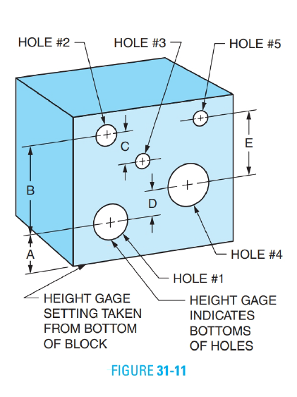
The hole locations of the block in Figure 31-11 are checked by placing the block on a surface plate and indicating the bottom of each hole using a height gage with an indicator attachment. Determine the height gage settings from the bottom of the part to the bottom of the holes. Assume that the actual hole diameters and locations are the same as the given dimensions. The setting for Hole Number 1 is given.
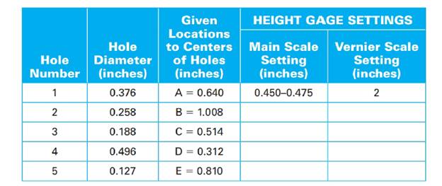
(1)
The main scale setting.
The vernier scale setting.
Answer to Problem 26A
The main scale setting is
The vernier scale setting is
Explanation of Solution
Given information:
The diameter of the hole
The figure below shows the hole locations from surface plate.
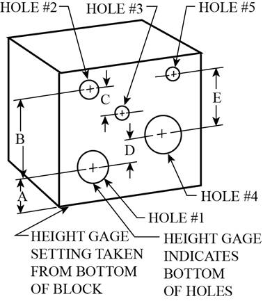
Figure-(1)
Write the expression for the height gauge settings.
Here, the distance between the center of the holes is
Write the expression for the relationship between vernier scale setting and main scale setting.
Here, the height gauge setting is
Calculation:
Substitute
The
Hence, the main scale setting is
As the lower value is required for the measurement, taking
Substitute
Hence, the vernier scale setting is
Conclusion:
The main scale setting is
The vernier scale setting is
(2)
The main scale setting.
The vernier scale setting.
Answer to Problem 26A
The main scale setting is
The vernier scale setting is
Explanation of Solution
Given information:
The diameter of the hole
Write the expression for the height gauge settings.
Here, the distance between the centers of hole
Calculation:
Substitute
The
Hence, the main scale setting is
As the lower value is required for the measurement, taking
Substitute
Hence, the vernier scale setting is
Conclusion:
The main scale setting is
The vernier scale setting is
(3)
The main scale setting.
The vernier scale setting.
Answer to Problem 26A
The main scale setting is
The vernier scale setting is
Explanation of Solution
Given information:
The diameter of the hole
Write the expression for the height gauge settings.
Here, the distance between the centers of hole
Calculation:
Substitute
The
Hence, the main scale setting is
As the lower value is required for the measurement, taking
Substitute
Hence, the vernier scale setting is
Conclusion:
The main scale setting is
The vernier scale setting is
(4)
The main scale setting.
The vernier scale setting.
Answer to Problem 26A
The main scale setting is
The vernier scale setting is
Explanation of Solution
Given information:
The diameter of the hole
Write the expression for the height gauge settings.
Here, the distance between hole
Calculation:
Substitute
The
Hence, the main scale setting is
As the lower value is required for the measurement, taking
Substitute
Hence, the vernier scale setting is
Conclusion:
The main scale setting is
The vernier scale setting is
(5)
The main scale setting.
The vernier scale setting.
Answer to Problem 26A
The main scale setting is
The vernier scale setting is
Explanation of Solution
Given information:
The diameter of the hole
Write the expression for the height gauge settings.
Here, the distance between hole
Calculation:
Substitute
The
Hence, the main scale setting is
As the lower value is required for the measurement, taking
Substitute
Hence, the vernier scale setting is
Conclusion:
The main scale setting is
The vernier scale setting is
Want to see more full solutions like this?
Chapter 31 Solutions
Mathematics For Machine Technology


- Refer to the shaft shown in Figure 6-4. Determine the missing dimensions in the table using the dimensions given. All dimensions are in inches.arrow_forwardAll sections of the block in Figure 13-9 are equal in length. Determine the length A to the nearest thousandth millimeter.arrow_forwardThis sheet metal section shown in Figure 5-5 has five sets of drilled holes: A, B, C, D, and E. The holes within a set are equally spaced in the horizontal direction. Compute the horizontal distance between two consecutive holes for each set. All dimensions are in inches. A=_B=_C=_D=_E=_arrow_forward
- Use Figure 10-4 to answer Exercises 4 and 5. All dimensions are in inches. 5. Determine the length of E in Figure 10-4.arrow_forwardThe machined plate distances shown in Figure 41-3 are dimensioned, in millimeters, in terms of x. Determine dimensions A-G.arrow_forwardDetermine the maximum and minimum permissible wall thickness of the steel sleeve shown in Figure 29-15.All dimensions are in millimeters.arrow_forward
- A cross-sectional view of a bevel gear is shown in Figure 13-5. Given the diametral pitch and the number of gear teeth, determine the pitch diameter, the addendum, and thededendum. Round the answers to 4 decimal places.arrow_forwardThe length, L, of the point on any standard 118° included angle drill, as shown in Figure 12-5, can be calculated using the formula L=0.3 O where represents the diameter of the drill. Determine the lengths of the following drill points with the given diameters. Round to 3 decimal places for inches and 1 decimal place for millimeters. a. 12 b. 14 c. 38 d. 10 mm e. 25 mm f. 45 mmarrow_forwardThe distance between the centers of two holes can be checked with a vernier caliper. The position of the caliper in measuring the inside distance between two holes is shown in Figure 29-10. To determine the setting on the caliper, subtract the radius of each hole (one-half the diameter) from the center distance. In Exercises 19 through 23, give the hole diameters and the distances between centers. For each, determine (1) the main scale setting and (2) the vernier scale setting. All dimensions are in inches.arrow_forward
- The distance between the centers of two holes can be checked with a vernier caliper. The position of the caliper in measuring the inside distance between two holes is shown in Figure 29-10. To determine the setting on the caliper, subtract the radius of each hole (one-half the diameter) from the center distance. In Exercises 19 through 23, give the hole diameters and the distances between centers. For each, determine (1) the main scale setting and (2) the vernier scale setting. All dimensions are in inches 23. Note: Hole tolerances and center distance tolerances are shown. Maximum and minimum vernier scale settings are required.arrow_forwardFour sets of equally spaced holes are shown in the machined plate in Figure 13-4. Determine dimensions A, B, C, and D to 2 decimal places. All dimensions are in millimeters. A=_B=_C=_D=_arrow_forwardMeasure the lengths of dimensions a-f in Figure 30-25 to the nearer whole millimeter.arrow_forward
- Mathematics For Machine TechnologyAdvanced MathISBN:9781337798310Author:Peterson, John.Publisher:Cengage Learning,
 Elementary Geometry for College StudentsGeometryISBN:9781285195698Author:Daniel C. Alexander, Geralyn M. KoeberleinPublisher:Cengage Learning