
Videos
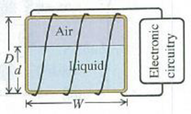
CP A Volume Gauge. A tank containing a liquid has turns of wire wrapped around it, causing it to act like an inductor. The liquid content of the tank can be measured by using its inductance to determine the height of the liquid in the tank. The inductance of the tank changes from a value of L0 corresponding to a relative permeability of 1 when the tank is empty to a value of Lf corresponding to a relative permeability of Km (the relative permeability of the liquid) when the tank is full. The appropriate electronic circuitry can determine the inductance to five significant figures and thus the effective relative permeability of the combined air and liquid within the rectangular cavity of the tank. The four sides of the tank each have width W and height D (Fig. P30.70). The height of the liquid in the tank is d. You can ignore any fringing effects and assume that the relative permeability of the material of which the tank is made can be ignored, (a) Derive an expression for d as a function of L, the inductance corresponding to a certain fluid height. L0. Lf, and D. (b) What is the inductance (to five significant figures) for a tank
Figure P30.70
Want to see the full answer?
Check out a sample textbook solution
Chapter 30 Solutions
University Physics (14th Edition)
Additional Science Textbook Solutions
The Cosmic Perspective
Tutorials in Introductory Physics
Essential University Physics: Volume 2 (3rd Edition)
Cosmic Perspective Fundamentals
College Physics
Essential University Physics (3rd Edition)


- A solenoid 50 cm long is wound with 500 turns of wire. The cross-sectional area of the coil is 2.0 cm2. What is the self-inductance of the solenoid?arrow_forwardIn the LC circuit in Figure 33.11, the inductance is L = 19.8 mH and the capacitance is C = 19.6 mF. At some moment, UB = UE= 17.5 mJ. a. What is the maximum charge stored by the capacitor? b. What is the maximum current in the circuit? c. At t = 0, the capacitor is fully charged. Write an expression for the charge stored by the capacitor as a function of lime. d. Write an expression for the current as a function of time.arrow_forward(a) An inductor designed to filter high-frequency noise from power supplied to a personal computer is placed in series with the computer. What minimum inductance should it have to produce a 2.00 k(reactance for 15.0 kHz noise? (b) What is its reactance at 60.0 Hz?arrow_forward
- In the transformer shown in Figure P33.51, the load resistance RL is 50.0 . The turns ratio N1/N2 is 2.50, anti the rms source voltage is Vs = 80.0 V. If a voltmeter across the load resistance measures an rms voltage of 25.0 V, what is the source resistance Rs?arrow_forwardA coil with a self-inductance of 2.0 H carries a current that varies with time according to I(t) = (2.0 A)sin 120t . Find an expression for the emf induced in the coil.arrow_forwardA series RLC circuit has resistance R = 50.0 and inductance L. = 0.500 H. (a) Find the circuits capacitance C if the voltage source operates at a frequency of f = 60.0 Hz and the impedance is Z = R = 50.0 . (b) What is the phase angle between the current and the voltage?arrow_forward
- When a wire carries an AC current with a known frequency, you can use a Rogowski coil to determine the amplitude Imax of the current without disconnecting the wire to shunt the current through a meter. The Rogowski coil, shown in Figure P23.8, simply clips around the wire. It consists of a toroidal conductor wrapped around a circular return cord. Let n represent the number of turns in the toroid per unit distance along it. Let A represent the cross-sectional area of the toroid. Let I(t) = Imax sin t represent the current to be measured. (a) Show that the amplitude of the emf induced in the Rogowski coil is Emax=0nAImax. (b) Explain why the wire carrying the unknown current need not be at the center of the Rogowski coil and why the coil will not respond to nearby currents that it does not enclose. Figure P23.8arrow_forwardA step-up transformer connected to a 100-V line U used to supply a hydrogen-gas discharge tube with 5.0 kV (rms). The tube dissipates 75 W of power, (a) What is the ratio of the number of turns in the secondary winding to the number of turns in the primary winding? (b) What are the nns currents in the primary and secondary windings? (c) What is the effective resistance seen by the 110-V source?arrow_forwardA coil of 40 turns is wrapped around a long solenoid of cross-sectional area 7.5 × 10⁻³ m2. The solenoid is 0.50 m long and has 500 turns. (a) What is the mutual inductance of this system? (b) The outer coil is replaced by a coil of 40 turns whose radius is three times that of the solenoid. What is the mutual inductance of this configuration?arrow_forward
 Physics for Scientists and Engineers: Foundations...PhysicsISBN:9781133939146Author:Katz, Debora M.Publisher:Cengage Learning
 Principles of Physics: A Calculus-Based TextPhysicsISBN:9781133104261Author:Raymond A. Serway, John W. JewettPublisher:Cengage Learning
 Physics for Scientists and Engineers, Technology ...PhysicsISBN:9781305116399Author:Raymond A. Serway, John W. JewettPublisher:Cengage Learning
 College PhysicsPhysicsISBN:9781285737027Author:Raymond A. Serway, Chris VuillePublisher:Cengage Learning
 College PhysicsPhysicsISBN:9781938168000Author:Paul Peter Urone, Roger HinrichsPublisher:OpenStax College