Concept explainers
(a)
The magnitude and direction of magnetic field at point
(a)
Answer to Problem 15P
The magnitude is
Explanation of Solution
Write the expression to obtain the magnetic field along the conductor.
Here,
The arrangement of the conductors is as shown in the figure below.
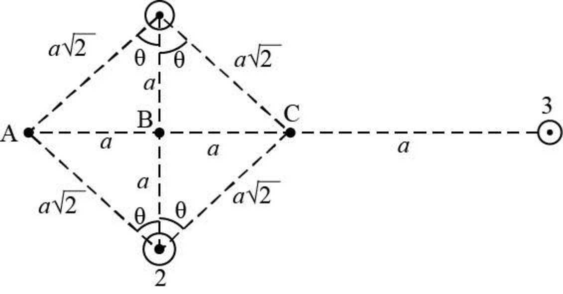
Figure-(1)
Write the expression to obtain the magnetic field at point
Here,
Conclusion:
Substitute
Further substitute
Substitute
Further substitute
Substitute
Further substitute
Substitute
Based on right hand thumb rule the direction of magnetic field at point
Therefore, the magnitude is
(b)
The magnitude and direction of magnetic field at point
(b)
Answer to Problem 15P
The magnitude is
Explanation of Solution
Write the expression to obtain the magnetic field at point
Here,
The magnetic field due to conductor
Conclusion:
Substitute
Further substitute
Substitute
Based on right hand thumb rule the direction of magnetic field at point
Therefore, the magnitude is
(c)
The magnitude and direction of magnetic field at point
(c)
Answer to Problem 15P
The magnitude is
Explanation of Solution
Write the expression to obtain the magnetic field at point
Here,
Conclusion:
Substitute
Further substitute
Substitute
Further substitute
Substitute
Further substitute
Substitute
Further solve the above equation.
Therefore, the magnitude is
Want to see more full solutions like this?
Chapter 30 Solutions
Physics For Scientists And Engineers With Modern Physics, 9th Edition, The Ohio State University


- Two infinitely long current-carrying wires run parallel in the xy plane and are each a distance d = 11.0 cm from the y axis (Fig. P30.83). The current in both wires is I = 5.00 A in the negative y direction. a. Draw a sketch of the magnetic field pattern in the xz plane due to the two wires. What is the magnitude of the magnetic field due to the two wires b. at the origin and c. as a function of z along the z axis, at x = y = 0? FIGURE P30.83arrow_forwardFigure P30.10 shows a circular current-carrying wire. Using the coordinate system indicated (with the z axis out of the page), state the direction of the magnetic field at points A and B.arrow_forwardA circular coil 15.0 cm in radius and composed of 145 tightly wound turns carries a current of 2.50 A in the counterclockwise direction, where the plane of the coil makes an angle of 15.0 with the y axis (Fig. P30.73). The coil is free to rotate about the z axis and is placed in a region with a uniform magnetic field given by B=1.35jT. a. What is the magnitude of the magnetic torque on the coil? b. In what direction will the coil rotate? FIGURE P30.73arrow_forward
- A toroid has a major radius R and a minor radius r and is tightly wound with N turns of wire on a hollow cardboard torus. Figure P31.6 shows half of this toroid, allowing us to see its cross section. If R r, the magnetic field in the region enclosed by the wire is essentially the same as the magnetic field of a solenoid that has been bent into a large circle of radius R. Modeling the field as the uniform field of a long solenoid, show that the inductance of such a toroid is approximately L=120N2r2R Figure P31.6arrow_forwardA wire is bent in the form of a square loop with sides of length L (Fig. P30.24). If a steady current I flows in the loop, determine the magnitude of the magnetic field at point P in the center of the square. FIGURE P30.24arrow_forward
 Principles of Physics: A Calculus-Based TextPhysicsISBN:9781133104261Author:Raymond A. Serway, John W. JewettPublisher:Cengage Learning
 Physics for Scientists and Engineers: Foundations...PhysicsISBN:9781133939146Author:Katz, Debora M.Publisher:Cengage Learning
 Physics for Scientists and Engineers with Modern ...PhysicsISBN:9781337553292Author:Raymond A. Serway, John W. JewettPublisher:Cengage Learning
 Physics for Scientists and EngineersPhysicsISBN:9781337553278Author:Raymond A. Serway, John W. JewettPublisher:Cengage Learning
 Physics for Scientists and Engineers, Technology ...PhysicsISBN:9781305116399Author:Raymond A. Serway, John W. JewettPublisher:Cengage Learning