
Concept explainers
Videos
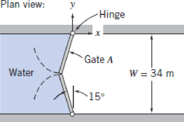
Gates in the Poe Lock at Sault Ste. Marie, Michigan, close a channel W = 34 m wide, L = 360 m long, and D = 10 m deep. The geometry of one pair of gates is shown; each gate is hinged at the channel wall. When closed, the gate edges are forced together at the center of the channel by water pressure. Evaluate the force exerted by the water on gate A. Determine the magnitude and direction of the force components exerted by the gate on the hinge. Neglect the weight of the gate.
Want to see the full answer?
Check out a sample textbook solution
Chapter 3 Solutions
Fox and McDonald's Introduction to Fluid Mechanics
Additional Engineering Textbook Solutions
DeGarmo's Materials and Processes in Manufacturing
Thinking Like an Engineer: An Active Learning Approach (3rd Edition)
INTERNATIONAL EDITION---Engineering Mechanics: Statics, 14th edition (SI unit)
Manufacturing Engineering & Technology
Applied Statics and Strength of Materials (6th Edition)


- The A have 4.8 m wide sluice gate "ab" shown, tangent to vertical wall at "a", holds back Water. The surface of the gate in contact with the water can be taken as part of a cylinder with radius of B at 4.5m. The angle (theta) is C at 31°. Determine the following: a. Horizontal force acting on curve b. Location of horizontal force from the water surface. c. Total Force on the curve I W.S. Imarrow_forwardA gate AB 4 ft long and 2 ft wide is held in position shown due to the spring whose constant is 96.0 Ibf/in. The spring is located compressed 1.5 ft in such a way as to keep the gate in equilibrium. Assume that on the gate (which moves through a circular sector BD as shown in Fig. figure), the force due to the spring is always horizontal. Determine the height d of the water.arrow_forwardOcean Marsh d = 9 ft 5.79 A freshwater marsh is drained to the ocean through an automatic tide gate that is 4 ft wide and 3 ft high. The gate is ħeld by hinges located along its top edge at A and bears on a sill at B. At a given time, the water levels in the marsh and in the ocean are h = 6 ft and d = 9 ft, respectively. Determine the force exerted by the sill on the gate at B and the hinge reaction at A. (Specific weight of salt water = 64 lb/ft³.) h =6 ft 3 ft B Fig. P5.79arrow_forward
- Problem 2: Hydrostatics The Uniontown Dam on the Ohio River uses a Tainter gate to control water flow into the river; the gate width is w=35 m into the page. Determine the magnitude, direction, and line of action of the force from the water acting on the gate. (10 pts) R = 20 m D= 10 m Water Figure 2: Tainter gate.arrow_forwardFigure 3 shows the plan view (top view) of a pair of gates which are hinged at the water channel walls. The channel has a depth of 9 m and a width of 40 m. When the gates close, the gate edges are forced together at the center of the channel by water pressure. While neglecting the weight of the gates determine: (a) The force exerted by the water on one gate (b) The magnitude and direction of the force components exerted by the gate in part (a) on the hinge. -Hinge Water 20°arrow_forward3. Gate AB is 1.5 m wide into the paper, hinged at A, and restrained by a stop at B. The water is at 20°C (density = 998 kg/m³). Compute (a) the force on stop B (b) the reactions at A if the water depth h = 3 m. V h Water S B (White, 2011) Pa 1.2 marrow_forward
- Problem 5. From the given figure, the spillway gate CD is in the form of parabolic segment with a length of 3m. The head of water is 4m and n=2m. Determine the following: a. Magnitude of the horizontal component Fn of the hydrostatic force acting on the gate b. Magnitude of the Vertical component F, of the hydrostatic force acting on the gate c. distance "z" of horizontal component from the bottom of the gate d. distance "s" of the vertical component from C Darrow_forwardThe hemispherical body (r=0.6m ) projects into a tank. Find the horizontal and vertical forces acting on the hemispherical projection for the following cases: (a) the tank is full of water with the free surface 1.5m above A; (6) the tank contains CCl, ( s=1.59) to the level of A overlain with water having its free surface 1.5m above A; (c) the tank is closed and contains Exercise 3 only gas at a pressure of 41368 N/m²;arrow_forward95 bläi 5 In the Fig. below is shown the * cross-section of the tank full of water under pressure. The length of the tank is 3 m. An empty cylinder lies along the length of the tank on one of its corners as shown. The horizontal component of the force acting on the curved surface ABC of * :the cylinder is 28 kN/m A r= 1.0m Tank full of water Empty cylinderarrow_forward
- 5. A 3-m-long (in the direction perpendicular to the paper) curved gate is located in the side of a reservoir. The gate forms a quarter of a circle whose radius is 2 m. Determine the magnitude of the horizontal and vertical components of the force that is required to hold the gate in place (ignore the self weight of the gate). 6 m Water X-2 2 m Gatearrow_forward(b) The water side of the wall of a 100-m-long dam is a quarter circle with a radius of 10 m as shown in Figure Q1(b). Determine the hydrostatic force on the dam and its line of action when the dam is filled to the rim. Fy=0 R= 10 m FH Figure Q1(b) Horizontal and vertical force on the quarter circle of a damarrow_forwardFind the magnitude and depth of the point of application of the force on circular gate shown in figure if h=5 ft and D=4 ft dia. Water Circular gate 60 dia Darrow_forward
 Elements Of ElectromagneticsMechanical EngineeringISBN:9780190698614Author:Sadiku, Matthew N. O.Publisher:Oxford University Press
 Mechanics of Materials (10th Edition)Mechanical EngineeringISBN:9780134319650Author:Russell C. HibbelerPublisher:PEARSON
 Thermodynamics: An Engineering ApproachMechanical EngineeringISBN:9781259822674Author:Yunus A. Cengel Dr., Michael A. BolesPublisher:McGraw-Hill Education
 Control Systems EngineeringMechanical EngineeringISBN:9781118170519Author:Norman S. NisePublisher:WILEY
 Mechanics of Materials (MindTap Course List)Mechanical EngineeringISBN:9781337093347Author:Barry J. Goodno, James M. GerePublisher:Cengage Learning
 Engineering Mechanics: StaticsMechanical EngineeringISBN:9781118807330Author:James L. Meriam, L. G. Kraige, J. N. BoltonPublisher:WILEY