
Fundamentals of Electromagnetics with Engineering Applications
1st Edition
ISBN: 9780470105757
Author: Stuart M. Wentworth
Publisher: Wiley, John & Sons, Incorporated
expand_more
expand_more
format_list_bulleted
Concept explainers
Videos
Textbook Question
Chapter 3, Problem 3.63P
Suppose the 2.0-cm-diameter core of the toroid in Figure 3.49a is characterized by the magnetization curve of Figure 3.60. The toroid has a mean radius of 60. cm. For 10. A of current driven through 100 loops of wire, find the magnetic field intensity in the 1.0-mm gap.
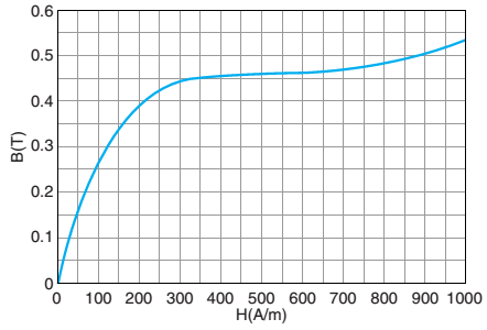
Figure 3.60 Magnetization curve for Problem 3.63.
Expert Solution & Answer
Want to see the full answer?
Check out a sample textbook solution
Students have asked these similar questions
Three long, parallel conductors cach carry a current of
I= 2.00 A. Figure P30.15 is an end view of the conduc-
tors, with each current coming out of the page. Taking
a = 1.00 cm, determine the magnitude and direction
of the magnetic field at (a) point A, (b) point B, and
(c) point C.
B
Figure 1 shows a ferromagnetic core with a relative permeability of 1850, the depth of the core
is 10 cm. The air gap on the core is 0.2 cm with effective area 5 % larger than their physical
size due to fringing effects. Given the number of turns N = 500 and current i = 2 x, where x is
the last digit of your student ID (example: EEE1705590, then i = 20 A):
(a) Find the total reluctance of the core and air gap. [CLO1-PL01:C2]
(b) Find the flux density of the air gap. [CLO1-PLO1:C2]
13 cm
23 cm
9 cm
5.6 сm
Air gap
31 cm
N turns
7 cm
Figure 1
Determine the mutual inductance between a very long straightwire and a conducting circular loop of radius “b” m set up “d” mapart on the same plane as shown figure.Problem:
Chapter 3 Solutions
Fundamentals of Electromagnetics with Engineering Applications
Ch. 3 - Find AB for the following: A=2ax3ay+4az,B=5ay1az...Ch. 3 - Prob. 3.2PCh. 3 - Given the vertices of a triangle...Ch. 3 - A segment of conductor on the z–axis extends...Ch. 3 - Prob. 3.5PCh. 3 - Prob. 3.6PCh. 3 - A square conductive loop in the shape 10.0 cm is...Ch. 3 - A conductive loop in the x–y plane is bounded by...Ch. 3 - How close do you have to be to the middle of a...Ch. 3 - For the ring of current described in MATLAB 3.2,...
Ch. 3 - A solenoid has 200 turns, is 10.0 cm long, and has...Ch. 3 - For the solenoid of the previous problem, plot the...Ch. 3 - Prob. 3.13PCh. 3 - Two infinite extent current sheets exist at z=2.0m...Ch. 3 - An infinite extent current sheet with K=6.0ayA/m...Ch. 3 - Given the field H=3y2ax, find the current passing...Ch. 3 - Given a 3.0–mm–radius solid wire centered on...Ch. 3 - Given a 2.0–cm–radius solid wire centered on...Ch. 3 - An infinitesimally thin metallic cylindrical shell...Ch. 3 - A cylindrical pipe with a 1.0–cm wall thickness...Ch. 3 - Prob. 3.21PCh. 3 - Prob. 3.22PCh. 3 - Consider the toroid in Figure 3.55 that is tightly...Ch. 3 - Find A for the following fields: A=3xy2/zax...Ch. 3 - Find J at (3m,60,4m) for H=(z/sin)a(2/cos)azA/mCh. 3 - Suppose H=y2ax+x2ayA/m .(a) Calculate HdL around...Ch. 3 - Prob. 3.27PCh. 3 - Suppose you have the field H=rcosaA/m. Now...Ch. 3 - Prob. 3.29PCh. 3 - Suppose an infinite extent sheet of current with...Ch. 3 - Prob. 3.31PCh. 3 - A 1.0nC charge with velocity 100.m/s in the y...Ch. 3 - A 1.0nC charge with velocity 100.m/s in the z...Ch. 3 - A 10.nC charged particle has a velocity...Ch. 3 - What electric field is required so that the...Ch. 3 - An electron (with rest mass Me=9.111031kg and...Ch. 3 - Prob. 3.37PCh. 3 - Prob. 3.38PCh. 3 - Prob. 3.39PCh. 3 - Suppose you have a pair of parallel lines each...Ch. 3 - In Figure 3.57, a 2.0-A line of current is shown...Ch. 3 - Modify MATLAB 3.4 to find the differential force...Ch. 3 - Prob. 3.43PCh. 3 - A square loop of 1.0-A current of side 4.0 cm is...Ch. 3 - A current sheet K=100axA/m exists at z=2.0cm. A...Ch. 3 - Prob. 3.46PCh. 3 - Prob. 3.47PCh. 3 - A solid nickel wire of diameter 2.0 mm evenly...Ch. 3 - Prob. 3.49PCh. 3 - The plane y = O separates two magnetic media....Ch. 3 - Prob. 3.52PCh. 3 - Prob. 3.53PCh. 3 - Prob. 3.54PCh. 3 - Prob. 3.55PCh. 3 - Prob. 3.56PCh. 3 - Prob. 3.57PCh. 3 - Prob. 3.58PCh. 3 - Prob. 3.59PCh. 3 - Prob. 3.60PCh. 3 - Prob. 3.61PCh. 3 - In Figure 3.59, a 2.0-cm-diameter toroidal core...Ch. 3 - Suppose the 2.0-cm-diameter core of the toroid in...Ch. 3 - Prob. 3.64PCh. 3 - Consider a 1.0-mm air gap in Figure 3.49a. The...
Knowledge Booster


Learn more about
Need a deep-dive on the concept behind this application? Look no further. Learn more about this topic, electrical-engineering and related others by exploring similar questions and additional content below.Similar questions
- a toroidal iron core with air gap problem...arrow_forwardA ferromagnetic core with a relative permeability of 1500 is shown in the given figure. The dimensions are as shown in the diagram, and the depth of the core is 5 cm. The air gaps on the left and right sides of the core are 0.050 and 0.070 cm, respectively. Because of fringing effects, the effective area of the air gaps is 5 percent larger than their physical size. If there are 300 turns in the coil wrapped around the center leg of the core and if the current in the coil is 1.0 A: (a) What are the flux values for the left, center and the right legs of the core? (b) What is the flux density in each air gap? 7 cm -30 cm- 7 em 30 ст 7 cm 30 cm -0.07 cm 300 turns 0.05 cm- 7 сm Core depth = 5 cmarrow_forwardA ferromagnetic core with a relative permeability of 1500 is shown in the given figure. The dimensions are as shown in the diagram, and the depth of the core is 5 cm. The air gaps on the left and right sides of the core are 0.050 and 0.070 cm, respectively. Because of fringing effects, the effective area of the air gaps is 5 percent larger than their physical size. If there are 300 turns in the coil wrapped around the center leg of the core and if the current in the coil is 1.0 A: (a) What are the flux values for the left, center and the right legs of the core? (b) What is the flux density in each air gap? 30 cm- 30 cm 7 cm 30 cm 0.07 cm 300 turns 0.05 cm cm Core depth - 5 cmarrow_forward
- A ferromagnetic core with a relative permeability of 1500 is shown in the given figure. The dimensions are as shown in the diagram, and the depth of the core is 5 cm. The air gaps on the left and right sides of the core are 0.050 and 0.070 cm, respectively. Because of fringing effects, the effective area of the air gaps is 5 percent larger than their physical size. If there are 300 turns in the coil wrapped around the center leg of the core and if the current in the coil is 1.0 A: (a) What are the flux values for the left, center and the right legs of the core? (b) What is the flux density in each air gap? 7 cm 30 cm 30cm- 7 cm 30 cm 0.07 cm 300 turns 0.05 cm 7 cm Activate Windows Go to Settings to activate Windows. Core depth - 5 cmarrow_forwardthe depth of the solid core is 5 cm. Assume that the relative permeability of the core is 1000 and remains constant and that the current in the coll is 4 A. ignore the fringing effects at the air gap and find the followingarrow_forwardFor the following magnetic core with an air gap and dimensions as shown in the figure. The depth of the core is 10 cm: 5 cm 25 cm 5 cm 15 cm Sm 5 cm Sm a) Find the reluctance of the core. The relative permeability 4, 2000. Hint: use depth to find the area. b) If the fringing effect increases the effective area of the air gap by 5% (from the area of the core), find the reluctance of the air gap. c) If the number of turns in the coil are N = 500, find the current i required to produce a magnetic field B, = 0.2 T in the air gap. %3Darrow_forward
- The force exerted on the length element dl at point P in the circular conductive ring in the figure, Please choose one: a.It is tangent to the ring on the note P. b.It's inward throughout the OP. C.It is outward throughout the OP. D.It is in the direction of the magnetic field.arrow_forwardQ2 (a): What is magnetic phase transformation? Discus and plot the phase transition from para to ferromagnetic. (b): Draw a magnetization curve of different feromagnetic materials and also discuss why different feromagnetic materials have different saturation levels.arrow_forward> Figure 1 shows a ferromagnetic core whose mean path length is 40 cm. There is a small gap of 0.05 cm in the structure of the otherwise whole core. The cross-sectional area of the core is 12cm?, the relative permeability of the core is 4000 and the coil of wire on the core has 400 turns. Assume that fringing in the air gap increases the effective cross-sectional area of the air gap by 5 percent. Given this information. Find the total reluctance of the flux path (iron plus air gap) and the current required to produce a flux density of 0.5 T in the air gap. N=400 0.05 cm A-12 cm - 40 cm Figure 1arrow_forward
- For this problem, please use the figure below. For the magnetic core, the mean length is 50 cm, cross-sectional area is 5 square cm, and relative permeability of the core is (8000/). If the length of the air gap is 0.00525 cm (yes, multiplied by pi) and assuming fringing in the air gap causes the effective cross-sectional area to increase by 5%, determine the total reluctance for this magnetic circuit. Express your answer in ampere-turns per weber, rounded off to the nearest thousand [1,000 A- t/Wb]. Figure for Problem 5 Core: mean length le area A. permeability j Coil: N turns Answer: Air gaparrow_forward4) A conductive material of uniform thickness h and intrinsic conductivity o is in the form of a quarter-circular nut with inner radius a and outer radius b as b - a shown in the figure. Find the resistance between the curved boundaries (a ver-bus) at this conductive nut.arrow_forward2) Vo voltage is applied to the metal parallel plate capacitor system given in the figure. The region between the plates is filled with dielectric material of &-2.4. Bottom plate grounded and d-2mm in the z-axis of the top plate when placed at z=0 are within distance. For tension in the interplate region boundary conditions: If V(z)-0 volts for z-0 and V(z)-Vo volts for z-d; a) Potential expression in the interplate region V=? b) Electric field strength E-? c) Electric flux density D-? d) Surface charge densities of the plates p.=?arrow_forward
arrow_back_ios
SEE MORE QUESTIONS
arrow_forward_ios
Recommended textbooks for you
 Introductory Circuit Analysis (13th Edition)Electrical EngineeringISBN:9780133923605Author:Robert L. BoylestadPublisher:PEARSON
 Delmar's Standard Textbook Of ElectricityElectrical EngineeringISBN:9781337900348Author:Stephen L. HermanPublisher:Cengage Learning
 Programmable Logic ControllersElectrical EngineeringISBN:9780073373843Author:Frank D. PetruzellaPublisher:McGraw-Hill Education
 Fundamentals of Electric CircuitsElectrical EngineeringISBN:9780078028229Author:Charles K Alexander, Matthew SadikuPublisher:McGraw-Hill Education
 Electric Circuits. (11th Edition)Electrical EngineeringISBN:9780134746968Author:James W. Nilsson, Susan RiedelPublisher:PEARSON
 Engineering ElectromagneticsElectrical EngineeringISBN:9780078028151Author:Hayt, William H. (william Hart), Jr, BUCK, John A.Publisher:Mcgraw-hill Education,
Introductory Circuit Analysis (13th Edition)
Electrical Engineering
ISBN:9780133923605
Author:Robert L. Boylestad
Publisher:PEARSON
Delmar's Standard Textbook Of Electricity
Electrical Engineering
ISBN:9781337900348
Author:Stephen L. Herman
Publisher:Cengage Learning
Programmable Logic Controllers
Electrical Engineering
ISBN:9780073373843
Author:Frank D. Petruzella
Publisher:McGraw-Hill Education
Fundamentals of Electric Circuits
Electrical Engineering
ISBN:9780078028229
Author:Charles K Alexander, Matthew Sadiku
Publisher:McGraw-Hill Education
Electric Circuits. (11th Edition)
Electrical Engineering
ISBN:9780134746968
Author:James W. Nilsson, Susan Riedel
Publisher:PEARSON
Engineering Electromagnetics
Electrical Engineering
ISBN:9780078028151
Author:Hayt, William H. (william Hart), Jr, BUCK, John A.
Publisher:Mcgraw-hill Education,
The Biot-Savart Law; Author: Jennifer Cash;https://www.youtube.com/watch?v=1BoIH6Quhiw;License: Standard Youtube License