
Applied Statics and Strength of Materials (6th Edition)
6th Edition
ISBN: 9780133840544
Author: George F. Limbrunner, Craig D'Allaird, Leonard Spiegel
Publisher: PEARSON
expand_more
expand_more
format_list_bulleted
Videos
Textbook Question
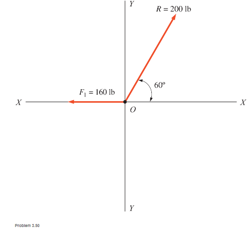
Chapter 3, Problem 3.50SP
The resultant and one-component force of a two-force concurrent force system are shown. Compute the other component force F2 (not shown) that would be required. Determine magnitude, direction, and sense.
Expert Solution & Answer

Learn your wayIncludes step-by-step video

schedule04:38
Chapter 3 Solutions
Applied Statics and Strength of Materials (6th Edition)
Ch. 3 - through 3.3 Determine the magnitude, direction,...Ch. 3 - Determine the magnitude, direction, and sense of...Ch. 3 - Determine the magnitude, direction, and sense of...Ch. 3 - Solve Problem 3.1 through 3.3 using the method of...Ch. 3 - Solve Problem 3.1 through 3.3 using the method of...Ch. 3 - through 3.6 Solve Problem 3.1 through 3.3 using...Ch. 3 - The 150-lb force shown is the resultant of two...Ch. 3 - Find the resultant force P exerted on the tree.Ch. 3 - Find the resultant force R exerted on the pole.Ch. 3 - Calculate the resultant force on the screw eye....
Ch. 3 - Determine the resultant of the coplanar concurrent...Ch. 3 - Use the parallelogram law to find the following...Ch. 3 - Prob. 3.13PCh. 3 - Determine the resultant of the coplanar concurrent...Ch. 3 - The resultant of the concurrent force system shown...Ch. 3 - Three force of 900 lb, 1000 lb, and 600 lb are...Ch. 3 - The four forces shown hade parallel lines of...Ch. 3 - Three coplanar concurrent forces act as shown. a....Ch. 3 - Four coplanar concurrent forces act as shown a....Ch. 3 - Determine the resultant of the four forces of...Ch. 3 - For the concrete wall and footing shown: a....Ch. 3 - Calculate the moment of the 550-lb force about...Ch. 3 - In Problem 3.22 , calculate the moment about point...Ch. 3 - Compute the moment about point A for the linkage...Ch. 3 - Compute the moment of the force F about point A...Ch. 3 - Determine the magnitude of the resultant of the...Ch. 3 - Determine the magnitude of the resultant of the...Ch. 3 - Determine the magnitude of the resultant of the...Ch. 3 - Determine the magnitude of the resultant of the...Ch. 3 - Determine the resultant and its location for the...Ch. 3 - Compute the magnitude, sense, and location of the...Ch. 3 - Compute the magnitude, sense, and location of the...Ch. 3 - Compute the magnitude and location of the...Ch. 3 - Determine the magnitude and location of the...Ch. 3 - Fresh water is impounded behind a dam to a height...Ch. 3 - Determine the magnitude and location of the...Ch. 3 - Determine the magnitude and location of the...Ch. 3 - Compute the magnitude and direction of the...Ch. 3 - Compute the magnitude and direction of the...Ch. 3 - Compute the magnitude and direction of the...Ch. 3 - A body is subjected to the following three...Ch. 3 - Determine the magnitude, direction, and sense of...Ch. 3 - Determine the magnitude, direction, and sense of...Ch. 3 - Determine the resultant of the load system shown....Ch. 3 - For the concrete structure shown, determine the...Ch. 3 - For the following computer problems, any...Ch. 3 - For the following computer problems, any...Ch. 3 - For the following computer problems, any...Ch. 3 - 3.49 Determine the magnitude, direction, and sense...Ch. 3 - The resultant and one-component force of a...Ch. 3 - The resultant force of a concurrent force system...Ch. 3 - Determine the magnitudes of forces P1 and P2 such...Ch. 3 - The resultant force of a concurrent force system...Ch. 3 - A hockey puck is acted on simultaneously by two...Ch. 3 - Determine the resultant force for each of the...Ch. 3 - Determine the resultant force for each of the...Ch. 3 - The resultant of the three concurrent forces shown...Ch. 3 - The transmission tower shown is subjected to a...Ch. 3 - A gravity-type masonry dam, as shown, depends on...Ch. 3 - The transfomer (as shown) must be lifted...Ch. 3 - Refer to the diagram for Problem 3.60 /. Assume...Ch. 3 - The plastic barrel tent anchor of Problem 2.11...Ch. 3 - Calculate the moment of the forces shown with...Ch. 3 - Determine the magnitude and location of the...Ch. 3 - Determine the moment (about point A) of the appied...Ch. 3 - The lift force on the wing of an aircraft is...Ch. 3 - A beam is subjected to distributed loads as shown....Ch. 3 - For the concrete gravity wall shown, determine the...Ch. 3 - Fresh water is impounded to a height of 8 ft...Ch. 3 - Plank, 2 in. by 10 in. in cross section and 5 ft...Ch. 3 - a. Compute the moment (about point A) of the...Ch. 3 - Determine the resultant of the three forces acting...Ch. 3 - a. Calculate the moments about points A and B due...Ch. 3 - Determine the magnitude of F1 and F2 shown such...Ch. 3 - Calculate the magnitude, direction, and sense of...
Additional Engineering Textbook Solutions
Find more solutions based on key concepts
Convert a volume of 6.35 liters to cubic nneters.
Applied Fluid Mechanics (7th Edition)
The moment of force about point O.
Engineering Mechanics: Statics & Dynamics (14th Edition)
Determine the speed of the brick just before it leaves the surface at B, the distanced d from the wall to where...
Engineering Mechanics: Dynamics (14th Edition)
Determine the magnitude and coordinate direction angles of the resultant force of the two forces acting on the ...
INTERNATIONAL EDITION---Engineering Mechanics: Statics, 14th edition (SI unit)
What parts are included in the vehicle chassis?
Automotive Technology: Principles, Diagnosis, and Service (5th Edition)
Determine the resultant internal loadings acting on the cross sections at points F and G of the frame. Probs. 7...
Statics and Mechanics of Materials (5th Edition)
Knowledge Booster


Learn more about
Need a deep-dive on the concept behind this application? Look no further. Learn more about this topic, mechanical-engineering and related others by exploring similar questions and additional content below.Similar questions
- The magnitudes of the three forces are F1=1.6kN,F2=1.2kN and F3=1.0kN. Compute their resultant in the form (a) R=Rxi+Ryj+Rzk; and (b) R=R.arrow_forwardThe values of Fz,Mx, and My for three force systems that are parallel to the z-axis are Determine the resultant of each force system and show it on a sketch of the coordinate system.arrow_forwardResolve the 360-lb force into components along the cables AB and AC. Use =60 and =40.arrow_forward
- The force systems in Figs. (a) and (b) have the same moment about the x- and y-axis. Determine the distances x and y.arrow_forwardThe four forces shown act on the rollers of an in-line skate. Determine the equivalent force-couple system, with the force acting at O (the ankle joint of the skater).arrow_forward
arrow_back_ios
arrow_forward_ios
Recommended textbooks for you
 International Edition---engineering Mechanics: St...Mechanical EngineeringISBN:9781305501607Author:Andrew Pytel And Jaan KiusalaasPublisher:CENGAGE L
International Edition---engineering Mechanics: St...
Mechanical Engineering
ISBN:9781305501607
Author:Andrew Pytel And Jaan Kiusalaas
Publisher:CENGAGE L
How to balance a see saw using moments example problem; Author: Engineer4Free;https://www.youtube.com/watch?v=d7tX37j-iHU;License: Standard Youtube License