
Videos
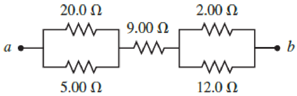
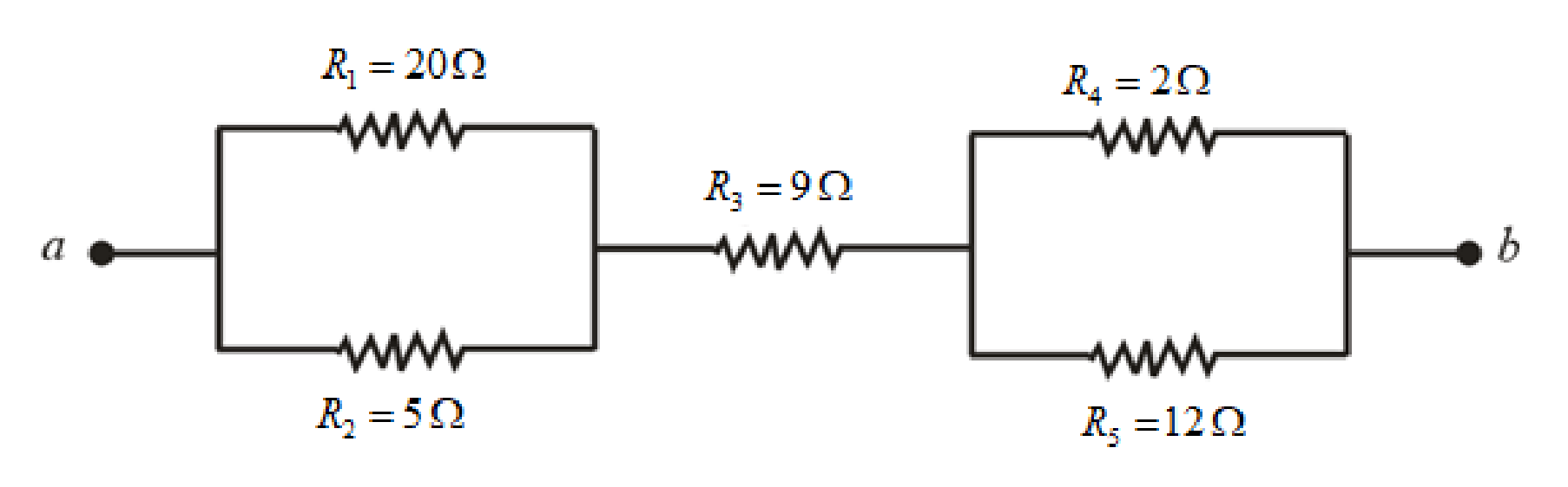
Figure P29.45 shows five resistors connected between terminals a and b.
- a. What is the equivalent resistance of this combination of resistors?
- b. What is the current through each resistor if a 24.0-V battery is connected across the terminals?
(a)
Find the equivalent resistance of the combination of the resistors.
Answer to Problem 45PQ
The equivalent resistance of the combination is
Explanation of Solution
Consider
Refer to figure above, the resistance
Write the equivalent resistance across the two resistances as.
Here,
Further, the resistances
Write the equivalent resistance across the two resistances as.
Here,
The circuit has
Write the equivalent resistance of the circuit as.
Here,
Conclusion:
Substitute
Rearrange the terms in above equation
Substitute
Rearrange the terms in above equation
Substitute
Thus, the equivalent resistance of the combination is
(b)
Find the current in each resistor in the circuit.
Answer to Problem 45PQ
The current flowing through
Explanation of Solution
Write the expression for the current drawn by the circuit from the battery as.
Here,
Write the expression for the voltage drop across
Here
Write the expression for the voltage drop across
Here
In a parallel connection, the voltage drop across all the elements remains same. Therefore the voltage drop across
Write the expression for the current through
Here
Write the expression for the current through
Here
The resistance
Therefore, the current through the resistance
Conclusion:
Substitute
Substitute
Substitute
Substitute
Substitute
The current through
Substitute
Substitute
Thus, the current flowing through
Want to see more full solutions like this?
Chapter 29 Solutions
Physics for Scientists and Engineers: Foundations and Connections


- In Figure P29.81, N real batteries, each with an emf and internal resistance r, are connected in a closed ring. A resistor R can be connected across any two points of this ring, causing there to be n real batteries in one branch and N n resistors in the other branch. Find an expression for the current through the resistor R in this case.arrow_forwardFigure P29.41 shows three resistors (R1 = 14.0 , R2 = 8.00 , and R3 = 10.0 ) and two batteries connected in a circuit. a. What is the current in each of the resistors? b. How much power is delivered to each of the resistors?arrow_forwardWhat is the equivalent resistance between points a and b of the six resistors shown in Figure P29.70? FIGURE P29.70arrow_forward
- Figure P29.77 shows a circuit with two batteries and three resistors. a. How much current flows through the 2.00- resistor? b. What is the potential difference between points a and b in the circuit?arrow_forwardA Figure P29.35 shows a combination of six resistors with identical resistance R. What is the equivalent resistance between points a and b?arrow_forwardFigure P29.42 shows five resistors and two batteries connected in a circuit. What are the currents I1, I2, and I3? FIGURE P29.42arrow_forward
- A Each resistor shown in Figure P29.36 has resistance R. An ideal emf device () is connected to points a and b via two leads (not shown in the figure). Find an expression for the current through the emf device. FIGURE P29.36arrow_forwardFour resistors are connected to a battery as shown in Figure P27.15. (a) Determine the potential difference across each resistor in terms of . (b) Determine the current in each resistor in terms of I. (c) What If? If R3 is increased, explain what happens to the current in each of the resistors. (d) In the limit that R3 , what are the new values of the current in each resistor in terms of I, the original current in the battery? Figure P27.15arrow_forwardThe circuit in Figure P21.59 has been connected for a long time. (a) What is the potential difference across the capacitor? (b) If the battery is disconnected from the circuit, over what time interval does the capacitor discharge to one-tenth its initial voltage?arrow_forward
- Figure P29.46 shows a circuit with a 12.0-V battery connected to four resistors. How much power is delivered to each resistor?arrow_forwardThree 100- resistors are connected as shown in Figure P21.41 The maximum power that can safely be delivered to any one resistor is 25.0 W. (a) What is the maximum potential difference that can be applied to the terminals a and b? (b) For the voltage determined in part (a), what is the power delivered to each resistor? (c) What is the total power delivered to the combination of resistors?arrow_forward(a) What is the resistance of a 1.00102 , a 2.50k , and a 4.00k resistor connected in series? (b) In parallel?arrow_forward
 Physics for Scientists and Engineers: Foundations...PhysicsISBN:9781133939146Author:Katz, Debora M.Publisher:Cengage Learning
 Physics for Scientists and Engineers with Modern ...PhysicsISBN:9781337553292Author:Raymond A. Serway, John W. JewettPublisher:Cengage Learning
 Physics for Scientists and EngineersPhysicsISBN:9781337553278Author:Raymond A. Serway, John W. JewettPublisher:Cengage Learning
 Principles of Physics: A Calculus-Based TextPhysicsISBN:9781133104261Author:Raymond A. Serway, John W. JewettPublisher:Cengage Learning