Physics for Scientists and Engineers: Foundations and Connections
1st Edition
ISBN: 9781133939146
Author: Katz, Debora M.
Publisher: Cengage Learning
expand_more
expand_more
format_list_bulleted
Textbook Question
Chapter 29, Problem 37PQ
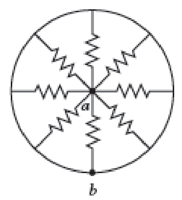
Each resistor shown in Figure P29.36 has a resistance of 100.0 Ω. An ideal emf device (120.0 V) is connected to points a and b via two leads (not shown in the figure). Find the current that flows through the emf device.

Expert Solution & Answer
Want to see the full answer?
Check out a sample textbook solution
Students have asked these similar questions
ROTATIONAL DYNAMICS
Question 01
A solid circular cylinder and a solid spherical ball of the same mass and radius are rolling
together down the same inclined. Calculate the ratio of their kinetic energy. Assume pure
rolling motion Question 02
A sphere and cylinder of the same mass and radius start from ret at the same point and more
down the same plane inclined at 30° to the horizontal
Which body gets the bottom first and what is its acceleration
b) What angle of inclination of the plane is needed to give the slower body the same
acceleration
Question 03
i)
Define the angular velocity of a rotating body and give its SI unit
A car wheel has its angular velocity changing from 2rads to 30 rads
seconds. If the radius of the wheel is 400mm. calculate
ii)
The angular acceleration
iii)
The tangential linear acceleration of a point on the rim of the wheel
Question 04
in 20
Question B3
Consider the following FLRW spacetime:
t2
ds² = -dt² +
(dx²
+ dy²+ dz²),
t2
where t is a constant.
a)
State whether this universe is spatially open, closed or flat.
[2 marks]
b) Determine the Hubble factor H(t), and represent it in a (roughly drawn) plot as a function
of time t, starting at t = 0.
[3 marks]
c) Taking galaxy A to be located at (x, y, z) = (0,0,0), determine the proper distance to galaxy
B located at (x, y, z) = (L, 0, 0). Determine the recessional velocity of galaxy B with respect
to galaxy A.
d) The Friedmann equations are
2
k
8πG
а
4πG
+
a²
(p+3p).
3
a
3
[5 marks]
Use these equations to determine the energy density p(t) and the pressure p(t) for the
FLRW spacetime specified at the top of the page.
[5 marks]
e) Given the result of question B3.d, state whether the FLRW universe in question is (i)
radiation-dominated, (ii) matter-dominated, (iii) cosmological-constant-dominated, or (iv)
none of the previous. Justify your answer.
f)
[5 marks]
A conformally…
SECTION B
Answer ONLY TWO questions in Section B
[Expect to use one single-sided A4 page for each Section-B sub question.]
Question B1
Consider the line element
where w is a constant.
ds²=-dt²+e2wt dx²,
a) Determine the components of the metric and of the inverse metric.
[2 marks]
b) Determine the Christoffel symbols. [See the Appendix of this document.]
[10 marks]
c)
Write down the geodesic equations.
[5 marks]
d) Show that e2wt it is a constant of geodesic motion.
[4 marks]
e)
Solve the geodesic equations for null geodesics.
[4 marks]
Chapter 29 Solutions
Physics for Scientists and Engineers: Foundations and Connections
Ch. 29.1 - What are the SI units of ?Ch. 29.1 - Prob. 29.2CECh. 29.2 - Prob. 29.3CECh. 29.4 - Prob. 29.5CECh. 29.4 - Prob. 29.6CECh. 29.5 - Prob. 29.7CECh. 29 - Study the symbols in Table 29.2. Then, without...Ch. 29 - Prob. 2PQCh. 29 - Prob. 3PQCh. 29 - Suppose you need to measure the potential...
Ch. 29 - Prob. 5PQCh. 29 - Prob. 6PQCh. 29 - A real battery (modeled as an ideal emf device in...Ch. 29 - Prob. 8PQCh. 29 - Two circuits made up of identical ideal emf...Ch. 29 - Prob. 10PQCh. 29 - Prob. 11PQCh. 29 - Prob. 12PQCh. 29 - Eight real batteries, each with an emf of 5.00 V...Ch. 29 - Prob. 14PQCh. 29 - Prob. 15PQCh. 29 - Prob. 16PQCh. 29 - Prob. 17PQCh. 29 - Prob. 18PQCh. 29 - Prob. 19PQCh. 29 - An ideal emf device with emf is connected to two...Ch. 29 - Prob. 21PQCh. 29 - Prob. 22PQCh. 29 - Prob. 23PQCh. 29 - Prob. 24PQCh. 29 - Prob. 25PQCh. 29 - Prob. 26PQCh. 29 - Determine the currents through the resistors R2,...Ch. 29 - The emf devices in the circuits shown in Figure...Ch. 29 - Prob. 29PQCh. 29 - Prob. 30PQCh. 29 - Prob. 31PQCh. 29 - Prob. 32PQCh. 29 - Prob. 33PQCh. 29 - Prob. 34PQCh. 29 - A Figure P29.35 shows a combination of six...Ch. 29 - A Each resistor shown in Figure P29.36 has...Ch. 29 - Each resistor shown in Figure P29.36 has a...Ch. 29 - Prob. 38PQCh. 29 - Prob. 39PQCh. 29 - The emf in Figure P29.40 is 4.54 V. The...Ch. 29 - Figure P29.41 shows three resistors (R1 = 14.0 ,...Ch. 29 - Figure P29.42 shows five resistors and two...Ch. 29 - The emfs in Figure P29.43 are 1 = 6.00 V and 2 =...Ch. 29 - Prob. 44PQCh. 29 - Figure P29.45 shows five resistors connected...Ch. 29 - Figure P29.46 shows a circuit with a 12.0-V...Ch. 29 - Two ideal emf devices are connected to a set of...Ch. 29 - Two ideal emf devices are connected to a set of...Ch. 29 - Three resistors with resistances R1 = R/2 and R2 =...Ch. 29 - Prob. 51PQCh. 29 - Prob. 52PQCh. 29 - Prob. 53PQCh. 29 - Prob. 55PQCh. 29 - At time t = 0, an RC circuit consists of a 12.0-V...Ch. 29 - A 210.0- resistor and an initially uncharged...Ch. 29 - Prob. 58PQCh. 29 - A real battery with internal resistance 0.500 and...Ch. 29 - Figure P29.60 shows a simple RC circuit with a...Ch. 29 - Prob. 61PQCh. 29 - Prob. 62PQCh. 29 - Prob. 63PQCh. 29 - Ralph has three resistors, R1, R2, and R3,...Ch. 29 - Prob. 65PQCh. 29 - An ideal emf device is connected to a set of...Ch. 29 - Prob. 67PQCh. 29 - An ideal emf device (24.0 V) is connected to a set...Ch. 29 - Prob. 69PQCh. 29 - What is the equivalent resistance between points a...Ch. 29 - A capacitor with initial charge Q0 is connected...Ch. 29 - Prob. 73PQCh. 29 - Prob. 74PQCh. 29 - Prob. 75PQCh. 29 - Prob. 76PQCh. 29 - Figure P29.77 shows a circuit with two batteries...Ch. 29 - In the RC circuit shown in Figure P29.78, an ideal...Ch. 29 - Prob. 79PQCh. 29 - Calculate the equivalent resistance between points...Ch. 29 - In Figure P29.81, N real batteries, each with an...Ch. 29 - Prob. 82PQCh. 29 - Prob. 83PQCh. 29 - Prob. 84PQCh. 29 - Figure P29.84 shows a circuit that consists of two...Ch. 29 - Prob. 86PQCh. 29 - Prob. 87PQCh. 29 - Prob. 88PQCh. 29 - Prob. 89PQCh. 29 - Prob. 90PQCh. 29 - Prob. 91PQCh. 29 - Prob. 92PQCh. 29 - Prob. 93PQCh. 29 - Prob. 94PQCh. 29 - Prob. 95PQ
Knowledge Booster
Learn more about
Need a deep-dive on the concept behind this application? Look no further. Learn more about this topic, physics and related others by exploring similar questions and additional content below.Similar questions
- Page 2 SECTION A Answer ALL questions in Section A [Expect to use one single-sided A4 page for each Section-A sub question.] Question A1 SPA6308 (2024) Consider Minkowski spacetime in Cartesian coordinates th = (t, x, y, z), such that ds² = dt² + dx² + dy² + dz². (a) Consider the vector with components V" = (1,-1,0,0). Determine V and V. V. (b) Consider now the coordinate system x' (u, v, y, z) such that u =t-x, v=t+x. [2 marks] Write down the line element, the metric, the Christoffel symbols and the Riemann curvature tensor in the new coordinates. [See the Appendix of this document.] [5 marks] (c) Determine V", that is, write the object in question A1.a in the coordinate system x'. Verify explicitly that V. V is invariant under the coordinate transformation. Question A2 [5 marks] Suppose that A, is a covector field, and consider the object Fv=AAμ. (a) Show explicitly that F is a tensor, that is, show that it transforms appropriately under a coordinate transformation. [5 marks] (b)…arrow_forwardHow does boiling point of water decreases as the altitude increases?arrow_forwardNo chatgpt pls will upvotearrow_forward
- 14 Z In figure, a closed surface with q=b= 0.4m/ C = 0.6m if the left edge of the closed surface at position X=a, if E is non-uniform and is given by € = (3 + 2x²) ŷ N/C, calculate the (3+2x²) net electric flux leaving the closed surface.arrow_forwardNo chatgpt pls will upvotearrow_forwardsuggest a reason ultrasound cleaning is better than cleaning by hand?arrow_forward
- Checkpoint 4 The figure shows four orientations of an electric di- pole in an external electric field. Rank the orienta- tions according to (a) the magnitude of the torque on the dipole and (b) the potential energy of the di- pole, greatest first. (1) (2) E (4)arrow_forwardWhat is integrated science. What is fractional distillation What is simple distillationarrow_forward19:39 · C Chegg 1 69% ✓ The compound beam is fixed at Ę and supported by rollers at A and B. There are pins at C and D. Take F=1700 lb. (Figure 1) Figure 800 lb ||-5- F 600 lb بتا D E C BO 10 ft 5 ft 4 ft-—— 6 ft — 5 ft- Solved Part A The compound beam is fixed at E and... Hình ảnh có thể có bản quyền. Tìm hiểu thêm Problem A-12 % Chia sẻ kip 800 lb Truy cập ) D Lưu of C 600 lb |-sa+ 10ft 5ft 4ft6ft D E 5 ft- Trying Cheaa Những kết quả này có hữu ích không? There are pins at C and D To F-1200 Egue!) Chegg Solved The compound b... Có Không ☑ ||| Chegg 10 וחarrow_forward
arrow_back_ios
SEE MORE QUESTIONS
arrow_forward_ios
Recommended textbooks for you
 Physics for Scientists and Engineers: Foundations...PhysicsISBN:9781133939146Author:Katz, Debora M.Publisher:Cengage Learning
 Physics for Scientists and Engineers with Modern ...PhysicsISBN:9781337553292Author:Raymond A. Serway, John W. JewettPublisher:Cengage Learning
 Principles of Physics: A Calculus-Based TextPhysicsISBN:9781133104261Author:Raymond A. Serway, John W. JewettPublisher:Cengage Learning
 Physics for Scientists and EngineersPhysicsISBN:9781337553278Author:Raymond A. Serway, John W. JewettPublisher:Cengage Learning
 College PhysicsPhysicsISBN:9781938168000Author:Paul Peter Urone, Roger HinrichsPublisher:OpenStax College
 Physics for Scientists and Engineers, Technology ...PhysicsISBN:9781305116399Author:Raymond A. Serway, John W. JewettPublisher:Cengage Learning

Physics for Scientists and Engineers: Foundations...
Physics
ISBN:9781133939146
Author:Katz, Debora M.
Publisher:Cengage Learning

Physics for Scientists and Engineers with Modern ...
Physics
ISBN:9781337553292
Author:Raymond A. Serway, John W. Jewett
Publisher:Cengage Learning

Principles of Physics: A Calculus-Based Text
Physics
ISBN:9781133104261
Author:Raymond A. Serway, John W. Jewett
Publisher:Cengage Learning

Physics for Scientists and Engineers
Physics
ISBN:9781337553278
Author:Raymond A. Serway, John W. Jewett
Publisher:Cengage Learning

College Physics
Physics
ISBN:9781938168000
Author:Paul Peter Urone, Roger Hinrichs
Publisher:OpenStax College

Physics for Scientists and Engineers, Technology ...
Physics
ISBN:9781305116399
Author:Raymond A. Serway, John W. Jewett
Publisher:Cengage Learning
What is Electromagnetic Induction? | Faraday's Laws and Lenz Law | iKen | iKen Edu | iKen App; Author: Iken Edu;https://www.youtube.com/watch?v=3HyORmBip-w;License: Standard YouTube License, CC-BY