
Concept explainers
Videos
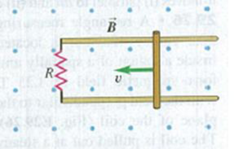
A 0.360-m-long metal bar is pulled to the left by an applied force F. The bar rides on parallel metal rails connected through a 45.0-Ω resistor, as shown in Fig. E29.31, so the apparatus makes a complete circuit. You can ignore the resistance of the bar and rails. The circuit is in a uniform 0.650-T magnetic field that is directed out of the plane of the figure. At the instant when the bar is moving to the left at 5.90 m/s, (a) is the induced current in the circuit clockwise or counterclockwise and (b) what is the rate at which the applied force is doing work on the bar?
Figure E29.31

Trending nowThis is a popular solution!

Chapter 29 Solutions
University Physics (14th Edition)
Additional Science Textbook Solutions
Sears And Zemansky's University Physics With Modern Physics
Physics: Principles with Applications
The Cosmic Perspective (8th Edition)
Conceptual Physics (12th Edition)
Lecture- Tutorials for Introductory Astronomy
Essential University Physics: Volume 1 (3rd Edition)


- Two frictionless conducting rails separated by l = 55.0 cm are connected through a 2.00- resistor, and the circuit is completed by a bar that is free to slide on the rails (Fig. P32.71). A uniform magnetic field of 5.00 T directed out of the page permeates the region, a. What is the magnitude of the force Fp that must be applied so that the bar moves with a constant speed of 1.25 m/s to the right? b. What is the rate at which energy is dissipated through the 2.00- resistor in the circuit?arrow_forwardConsider the system pictured in Figure P28.26. A 15.0-cm horizontal wire of mass 15.0 g is placed between two thin, vertical conductors, and a uniform magnetic field acts perpendicular to the page. The wire is free to move vertically without friction on the two vertical conductors. When a 5.00-A current is directed as shown in the figure, the horizontal wire moves upward at constant velocity in the presence of gravity. (a) What forces act on the horizontal wire, and (b) under what condition is the wire able to move upward at constant velocity? (c) Find the magnitude and direction of the minimum magnetic Field required to move the wire at constant speed. (d) What happens if the magnetic field exceeds this minimum value? Figure P28.26arrow_forwardA square loop whose sides are 6.0-cm long is made with copper wire of radius 1.0 mm. If a magnetic field perpendicular to the loop is changing at a rate of 5.0 mT/s, what is the current in the loop?arrow_forward
- A piece of insulated wire is shaped into a figure eight as shown in Figure P23.12. For simplicity, model the two halves of the figure eight as circles. The radius of the upper circle is 5.00 cm and that of the lower circle is 9.00 cm. The wire has a uniform resistance per unit length of 3.00 Ω/m. A uniform magnetic field is applied perpendicular to the plane of the two circles, in the direction shown. The magnetic field is increasing at a constant rate of 2.00 T/s. Find (a) the magnitude and (b) the direction of the induced current in the wire. Figure P23.12arrow_forwardReview. In studies of the possibility of migrating birds using the Earths magnetic field for navigation, birds have been fitted with coils as caps and collars as shown in Figure P22.39. (a) If the identical coils have radii of 1.20 cm and are 2.20 cm apart, with 50 turns of wire apiece, what current should they both carry to produce a magnetic field of 4.50 105 T halfway between them? (b) If the resistance of each coil is 210 V, what voltage should the battery supplying each coil have? (c) What power is delivered to each coil? Figure P22.39arrow_forwardA circular loop of wire with a radius of 4.0 cm is in a uniform magnetic field of magnitude 0.060 T. The plane of the loop is perpendicular to the direction of the magnetic field. In a time interval of 0.50 s, the magnetic field changes to the opposite direction with a magnitude of 0.040 T. What is the magnitude of the average emf induced in the loop? (a) 0.20 V (b) 0.025 V (c) 5.0 mV (d) 1.0 mV (e) 0.20 mVarrow_forward
- A constant magnetic field of 0.275 T points through a circular loop of wire with radius 3.50 cm as shown in Figure P32.1. a. What is the magnetic flux through the loop? b. Is a current induced in the loop? Explain. FIGURE P32.1arrow_forwardA toroid has a major radius R and a minor radius r and is tightly wound with N turns of wire on a hollow cardboard torus. Figure P31.6 shows half of this toroid, allowing us to see its cross section. If R r, the magnetic field in the region enclosed by the wire is essentially the same as the magnetic field of a solenoid that has been bent into a large circle of radius R. Modeling the field as the uniform field of a long solenoid, show that the inductance of such a toroid is approximately L=120N2r2R Figure P31.6arrow_forwardA wire is bent in the form of a square loop with sides of length L (Fig. P30.24). If a steady current I flows in the loop, determine the magnitude of the magnetic field at point P in the center of the square. FIGURE P30.24arrow_forward
 Physics for Scientists and Engineers: Foundations...PhysicsISBN:9781133939146Author:Katz, Debora M.Publisher:Cengage Learning
 Principles of Physics: A Calculus-Based TextPhysicsISBN:9781133104261Author:Raymond A. Serway, John W. JewettPublisher:Cengage Learning
 Physics for Scientists and Engineers with Modern ...PhysicsISBN:9781337553292Author:Raymond A. Serway, John W. JewettPublisher:Cengage Learning
 Physics for Scientists and EngineersPhysicsISBN:9781337553278Author:Raymond A. Serway, John W. JewettPublisher:Cengage Learning
 Physics for Scientists and Engineers, Technology ...PhysicsISBN:9781305116399Author:Raymond A. Serway, John W. JewettPublisher:Cengage Learning