
Physics for Scientists and Engineers: A Strategic Approach, Vol. 1 (Chs 1-21) (4th Edition)
4th Edition
ISBN: 9780134110684
Author: Randall D. Knight (Professor Emeritus)
Publisher: PEARSON
expand_more
expand_more
format_list_bulleted
Videos
Textbook Question
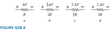
Chapter 28, Problem 6CQ
Rank in order, from largest to smallest, the powers
Expert Solution & Answer
Want to see the full answer?
Check out a sample textbook solution
Students have asked these similar questions
2o2
3052
352
552
652
2A
A. The power dissipated in the 3 Ohms resistor is
W.
B. The total voltage is
V.
C. The power dissipated in the 5 Ohms resistor is
W.
Round all answers to whole numbers.
V
+
R
w
с
The switch in the figure is thrown so that the battery is in series with the resistor and an
uncharged capacitor. After 1.9 time constants, what is the charge on the capacitor in
terms of the maximum charge, Qo? Supply the missing numerical factor below.
Q(1.9T) = (
)Qo
A 45 μF capacitor with an initial energy of 0.2 J is discharged through a 8 M resistor. What is the initial
charge on the capacitor?
The charge, Qo=
Units Select an answer ✓
What is the current through the resistor when the discharge starts?
The current, lo =
Units Select an answer ✓
Determine the potential difference across the capacitor and the rate at which the thermal energy is
dissipating in the resistance 7.2 min after the discharge starts.
The potential difference across C, Vc =
The power dissipated in R, P =
Units Select an answer
Units Select an answer ✓
Chapter 28 Solutions
Physics for Scientists and Engineers: A Strategic Approach, Vol. 1 (Chs 1-21) (4th Edition)
Ch. 28 - Rank in order, from largest to smallest, the...Ch. 28 - The tip of a flashlight bulb is touching the top...Ch. 28 - The wire is broken on the right side of the...Ch. 28 - The circuit of FIGURE Q28.4 has two resistors,...Ch. 28 - The circuit of FIGURE Q28.5 has two resistors,...Ch. 28 - Rank in order, from largest to smallest, the...Ch. 28 - Are the two resistors in FIGURE Q28.7 in series or...Ch. 28 - A battery with internal resistance r is connected...Ch. 28 - Initially bulbs A and B in FIGURE Q28.9 are...Ch. 28 - Bulbs A. B, and C in FIGURE Q28.1O axe identical,...
Ch. 28 - Bulbs A and B in FIGURE Q28.11 are identical, and...Ch. 28 - Prob. 12CQCh. 28 - FIGURE Q28.13 shows the voltage as a function of...Ch. 28 - Prob. 1EAPCh. 28 - Draw a circuit diagram for the circuit of FIGURE...Ch. 28 - Prob. 3EAPCh. 28 - Prob. 4EAPCh. 28 - a. What are the magnitude and direction of the...Ch. 28 - What is the magnitude of the potential difference...Ch. 28 - Prob. 7EAPCh. 28 - Prob. 8EAPCh. 28 - A 60 W lightbulb and a 100 W lightbulb are placed...Ch. 28 - Prob. 10EAPCh. 28 - The five identical bulbs in FIGURE EX2B.11 are all...Ch. 28 - Prob. 12EAPCh. 28 - Prob. 13EAPCh. 28 - A typical American family uses kWh of electricity...Ch. 28 - A waterbed heater uses 450 W of power. It is on 25...Ch. 28 - Prob. 16EAPCh. 28 - Prob. 17EAPCh. 28 - Prob. 18EAPCh. 28 - 19. The voltage across the terminals of a V...Ch. 28 - Prob. 20EAPCh. 28 - Prob. 21EAPCh. 28 - 22. Two of the three resistors in FIGURE EX28.22...Ch. 28 - What is the value of resistor R in FIGURE EX28.23?Ch. 28 - Prob. 24EAPCh. 28 - What is the equivalent resistance between points a...Ch. 28 - What is the equivalent resistance between points a...Ch. 28 - Prob. 27EAPCh. 28 - Prob. 28EAPCh. 28 - Prob. 29EAPCh. 28 - Prob. 30EAPCh. 28 - Prob. 31EAPCh. 28 - Prob. 32EAPCh. 28 - Prob. 33EAPCh. 28 - What is the time constant for the discharge of the...Ch. 28 - A 10F capacitor initially charged to 20C is...Ch. 28 - Prob. 36EAPCh. 28 - Prob. 37EAPCh. 28 - A capacitor is discharged through a resistor. The...Ch. 28 - Prob. 39EAPCh. 28 - 40. A refrigerator has a 1000 W compressor, but...Ch. 28 - Prob. 41EAPCh. 28 - An electric eel develops a potential difference...Ch. 28 - You have a resistor, a resistor, a resistor, and a...Ch. 28 - A 2.0 -m-long, 1.0 -mm-diameter wire has a...Ch. 28 - What is the equivalent resistance between points a...Ch. 28 - What are the emf and internal resistance of the...Ch. 28 - A string of holiday lights can be wired in series,...Ch. 28 - The circuit shown in FIGURE P28.48 is inside a 15...Ch. 28 - Suppose you have resistors 2.5,3.5, and 4.5 and a...Ch. 28 - A lightbulb is in series with a resistor. The...Ch. 28 - Prob. 51EAPCh. 28 - Prob. 52EAPCh. 28 - Prob. 53EAPCh. 28 - Prob. 54EAPCh. 28 - What are the battery current Ibatand the potential...Ch. 28 - A battery is a voltage source, always providing...Ch. 28 - A circuit you’re building needs an ammeter that...Ch. 28 - For the circuit shown in FIGURE P28.58, find the...Ch. 28 - For the circuit shown in FIGURE P28.59, find the...Ch. 28 - For the circuit shown in FIGURE P28.60, find the...Ch. 28 - What is the current through the 20 resistor in...Ch. 28 - For the circuit shown in FIGURE P28.62, find the...Ch. 28 - What is the current through the 10 resistor in...Ch. 28 - For what emf does the 200 resistor in FIGURE...Ch. 28 - Prob. 65EAPCh. 28 - Prob. 66EAPCh. 28 - Prob. 67EAPCh. 28 - II A circuit you're using discharges a 20F...Ch. 28 - A 150F defibrillator capacitor is charged to 1500V...Ch. 28 - Prob. 70EAPCh. 28 - A 0.25F capacitor is charged to 50 V. It is then...Ch. 28 - Prob. 72EAPCh. 28 - Prob. 73EAPCh. 28 - The capacitors in FIGURE P28.74 are charged and...Ch. 28 - Prob. 75EAPCh. 28 - Prob. 76EAPCh. 28 - Prob. 77EAPCh. 28 - Prob. 78EAPCh. 28 - Prob. 79EAPCh. 28 - Prob. 80EAPCh. 28 - Prob. 81EAPCh. 28 - Prob. 82EAP
Knowledge Booster


Learn more about
Need a deep-dive on the concept behind this application? Look no further. Learn more about this topic, physics and related others by exploring similar questions and additional content below.Similar questions
- A lightbulb is connected to a variable power supply. As the potential across the bulb is varied, the resulting current and the filaments temperature are measured. The data are listed in Table P28.38. a. Find R for each entry in Table P28.38, and then plot R as a function of T. b. Assume that room temperature is at 293 K. Find R0 (resistance at room temperature). Comment on your result.arrow_forwardA 12.0-V emf automobile battery has a terminal voltage of 16.0 V when being charged by a current of 10.0 A. (a) What is the battery’s internal resistance? (b) What power is dissipated inside the battery? (c) At what rate (in °C/min ) will its temperature increase if its mass is 20.0 kg and it has a specific heat of 0.300 kcal/kg • °C, assuming no heat escapes?arrow_forwardA battery is used to charge a capacitor through a resistor as shown in Figure P27.44. Show that half the energy supplied by the battery appears as internal energy in the resistor and half is stored in the capacitor. Figure P27.44arrow_forward
- 5. A 6.00 uf capacitor with an initial charge of 1200 µC is discharged through a 4.0 M2 resistor. a) Calculate the magnitude of the current in the resistor 12.0 s after the resistor is connected across the terminals of the capacitor. VC = (1- e24) %3D 4E6 1.2NO -10 b) What is the charge that remains on the capacitor after 12.0s? 2=Q (1-e-Tha 1/241 T-24 See 2=4.7 x10- %3D c) How much energy has the capacitor dissipated through the resistor in those 12 s? (Hint: energy is the integral of the power with respect to time.) 12 8.31 xio4 12arrow_forwardMaterial with uniform resistivity p is formed into a wedge as shown in Figure P26.50. Show that the resistance between face A and face B of this wedge is L R= p In w(y2 – y,) Face A Face B Figure P26.50arrow_forwardChapter 27, Problem 041 In the figure &₁ = 3.70 V, E2 = 0.987 V, R₁ = 5.78 , R₂ = 2.86 , R3 = 5.98 2, and both batteries are ideal. What is the rate at which energy is dissipated in (a) R₁, (b) R₂, and (c) R3? What is the power of (d) battery 1 and (e) battery 2? www R₁ -18₁ ww R₂ R₂₂ Erf Chapter 27, Problem 055 SN In the figure Rs is to be adjusted in value by moving the sliding contact across it until points a and b are brought to the same potential. (One tests for this condition by momentarily connecting a sensitive ammeter between a and b; if these points are at the same potential, the ammeter will not deflect.) Express Rx in terms of Rs, R₁ and R₂ in the case when this adjustment is made. Rs Ro -Sliding contact O Farrow_forward
- la. This resistor has a resistance of 48002, and 32mA of current flows to the left into it. The right end of the resistor is at a potential of VR= 12.5V. What is the potential difference AV across the resistor? 1b. What is the potential VL of the left end of the resistor? 1c. What is the power output by the resistor? VLP 1d. What is the current that flows out of the resistor? resistor R=4800 I I= 32mA VR=12.5Varrow_forwardThe circuit in Figure P27.41 contains two resistors, R1 = 2.00 kΩ and R2 = 3.00 kΩ, and two capacitors, C1 = 2.00 μF and C2 = 3.00 μF, connected to a battery with emf ε = 120 V. If there are no charges on the capacitors before switch S is closed, determine the charges on capacitors (a) C1 and (b) C2 as functions of time, after the switch is closed.arrow_forwardIn Figure P28.67, suppose the switch has been closed for a length of time sufficiently long for the capacitor to become fully charged. (E = 8.50 V, r1 = 10 kN, and r2 = 16 kN.) 10.0 µF 3.00 k2 Figure P28.67 (a) Find the steady-state current in each resistor. I1 = 1.32 Your response differs significantly from the correct answer. Rework your solution from the beginning and check each step carefully. µA I2 = 4.32 Your response differs significantly from the correct answer. Rework your solution from the beginning and check each step carefully. µA I3-ko = 0 HA (b) Find the charge Q on the capacitor. 8.83 Your response differs from the correct answer by more than 10%. Double check your calculations. µC (c) The switch is opened at t = 0. Write an equation for the current IR, in R, as a function of time. O (327 µA)e-t/(0.190 s) O (275 µA)et/(0.190 s) O (275 µA)e-t/(0.190 s) O (327 µA)et/(0.190 s) (d) Find the time that it takes for the charge on the capacitor to fall to one-fifth its initial…arrow_forward
- The figure shows an ideal battery of emf = 13 V, a resistor of resistance R 6.3 2, and an uncharged capacitor of capacitance C 6.3 µF. After switch S is closed, what is the current through the resistor when the charge on the capacitor is 9.5 µC? - warrow_forwardA 60-MF capacitor is charged to 250 V and is then connected across a 1500 N resistor. The amount of charge on the capacitor after 9 ms is approximately 0.80 mC 2.4 mC 13.6 mC 1.6 mCarrow_forwardIn Figure P28.67, suppose the switch has been closed for a length of time sufficiently long for the capacitor to become fully charged. (E = 8.50 V, r1 = 10 kN, and r2 = 16 kN.) 10.0 µF 3.00 k2 Figure P28.67 (a) Find the steady-state current in each resistor. I = 327 HA I2 = 327 HA 13-kn = 0 HA (b) Find the charge Q on the capacitor. 52 (c) The switch is opened at t = 0. Write an equation for the current IR, in R2 as a function of time. O (327 HA)e-t/(0.190 s) O (275 µA)et/(0.190 s) O (275 µA)e-t/(0.190 s) O (327 µA)et/(0.190 s) (d) Find the time that it takes for the charge on the capacitor to fall to one-fifth its initial value. msarrow_forward
arrow_back_ios
SEE MORE QUESTIONS
arrow_forward_ios
Recommended textbooks for you
 Physics for Scientists and EngineersPhysicsISBN:9781337553278Author:Raymond A. Serway, John W. JewettPublisher:Cengage Learning
 Physics for Scientists and Engineers with Modern ...PhysicsISBN:9781337553292Author:Raymond A. Serway, John W. JewettPublisher:Cengage Learning
 Principles of Physics: A Calculus-Based TextPhysicsISBN:9781133104261Author:Raymond A. Serway, John W. JewettPublisher:Cengage Learning
 Physics for Scientists and Engineers: Foundations...PhysicsISBN:9781133939146Author:Katz, Debora M.Publisher:Cengage Learning
Physics for Scientists and Engineers
Physics
ISBN:9781337553278
Author:Raymond A. Serway, John W. Jewett
Publisher:Cengage Learning
Physics for Scientists and Engineers with Modern ...
Physics
ISBN:9781337553292
Author:Raymond A. Serway, John W. Jewett
Publisher:Cengage Learning
Principles of Physics: A Calculus-Based Text
Physics
ISBN:9781133104261
Author:Raymond A. Serway, John W. Jewett
Publisher:Cengage Learning
Physics for Scientists and Engineers: Foundations...
Physics
ISBN:9781133939146
Author:Katz, Debora M.
Publisher:Cengage Learning
DC Series circuits explained - The basics working principle; Author: The Engineering Mindset;https://www.youtube.com/watch?v=VV6tZ3Aqfuc;License: Standard YouTube License, CC-BY