Videos
(a)
The equivalent resistance of the circuit given.
(a)
Answer to Problem 60AP
The equivalent resistor of the circuit is
Explanation of Solution
Following figure shows the resistance connected a voltage source of
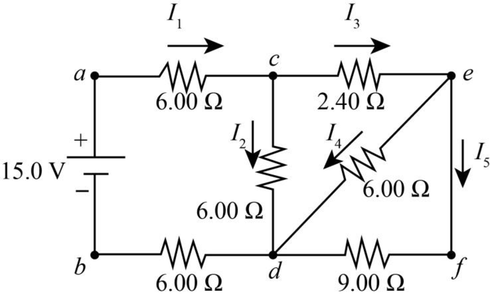
Figure-(1)
Write the expression for equivalent resistance connected in parallel.
Here,
Write the expression for equivalent resistance connected in series.
Here,
Following figure shows the rearranged circuit of the system from Figure (1) for better understanding.
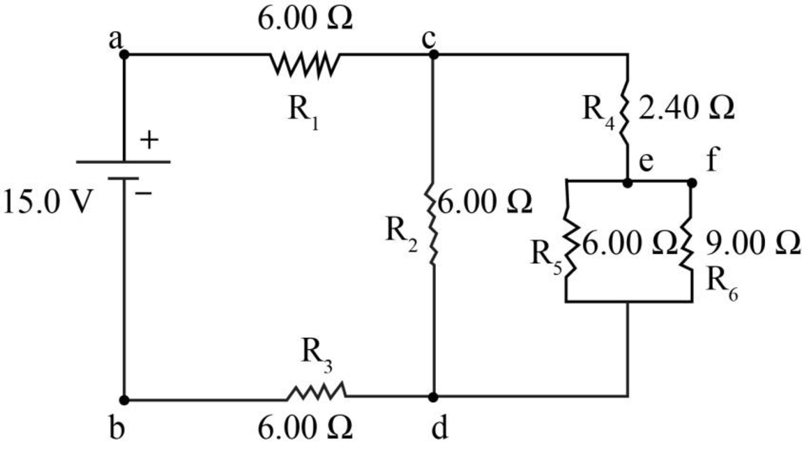
Figure-(2)
Conclusion:
From figure (2) calculate the equivalent resistance for
Substitute
Following figure shows the reduced circuit for the above equivalence.
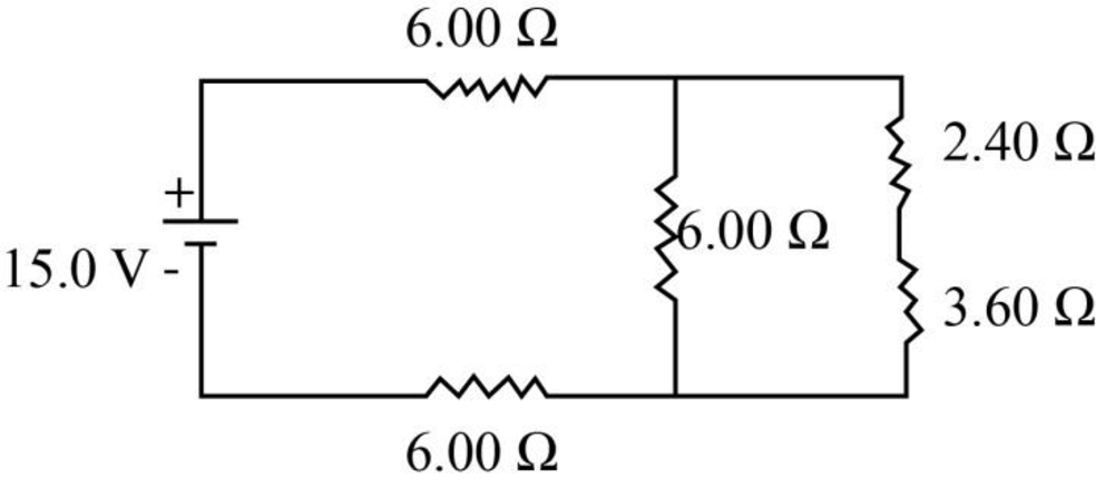
Figure-(3)
From figure (3) calculate the equivalent resistance for
Substitute
Following figure shows the reduced circuit for the above equivalence.
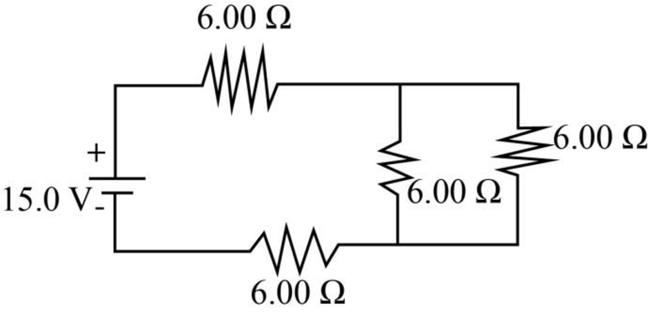
Figure-(4)
From figure (4) calculate the equivalent resistance for
Substitute
Following figure shows the reduced circuit for the above equivalence.
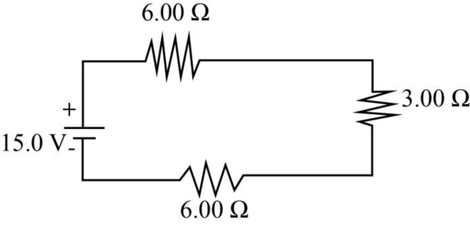
Figure-(5)
From figure (5) calculate the equivalent resistance for
Substitute
Therefore the equivalent resistor for the circuit is
(b)
The potential difference across each resistor.
(b)
Answer to Problem 60AP
voltage between junctions
Explanation of Solution
Write the expression for potential difference between two points of a resistor.
Here,
Conclusion:
Substitute
Calculate voltage drop across each
Substitute
Calculate voltage drop across
Substitute
Calculate current through
Substitute
Calculate voltage drop across
Substitute
Calculate the voltage drop across
Substitute
Therefore, voltage drop across the parallel resistor
Therefore, voltage between junctions
(c)
The each current indicated in the circuit.
(c)
Answer to Problem 60AP
ThecCurrent
Explanation of Solution
Rewrite Equation (III) to calculate
Conclusion:
Substitute
Substitute
Substitute
Substitute
Substitute
Therefore, current
(d)
The power delivered to each resistor.
(d)
Answer to Problem 60AP
Power delivered to resistor
Explanation of Solution
Write the expression for power in resistor.
Here,
Conclusion:
Substitute
Substitute
Substitute
Substitute
Substitute
Substitute
Therefore, power at resistor
Want to see more full solutions like this?
Chapter 28 Solutions
Physics for Scientists and Engineers With Modern Physics


- For the circuit shown in Figure P28.55. the ideal voltmeter reads 6.00 V and the ideal ammeter reads 3.00-k. Find (a) the value of K, (b) the emf of the battery, and (c) the voltage across the 3.00-kft resistor.arrow_forwardConsider the circuit shown in Figure P28.21 on page 860. (a) Find the voltage across the 3.00-0 resistor, (b) Find the current in the 3.00-12 resistor.arrow_forwardPower P0 = I0 V0 is delivered to a resistor of resistance R0. If the resistance is doubled (Rnew = 2R0) while the voltage is adjusted such that the current is constant, what are the ratios (a) Pnew/P0 and (b) Vnew/V0? If, instead, the resistance is held constant while Pnew = 2P0, what are the ratios (c) Vnew/V0, and (d) Inew/I0?arrow_forward
- (a) Can the circuit shown in Figure P18.29 be reduced to a single resistor connected to the batteries? Explain. (b) Find the magnitude of the current and its direction in each resistor. Figure P18.29arrow_forwardFigure P29.45 shows five resistors connected between terminals a and b. a. What is the equivalent resistance of this combination of resistors? b. What is the current through each resistor if a 24.0-V battery is connected across the terminals?arrow_forwardThe values of the components in a simple series RC circuit containing a switch (Fig. P21.53) are C = 1.00 F, R = 2.00 106 , and = 10.0 V. At the instant 10.0 s after the switch is closed, calculate (a) the charge on the capacitor, (b) the current in the resistor, (c) the rate at which energy is being stored in the capacitor, and (d) the rate at which energy is being delivered by the battery.arrow_forward
- What is the equivalent resistance between points a and b of the six resistors shown in Figure P29.70? FIGURE P29.70arrow_forwardAn automobile starter motor has an equivalent resistance of 0.0500 and is supplied by a 12.0-V battery with a 0.0100- internal resistance, (a) What is thecurrent to the motor? (b) What voltage is applied to it? (c) What power is supplied to the motor? (d) Repeat these calculations for when the battery connections are corroded and add 0.0900 to the circuit. (Significant problems are caused by even small amounts of unwanted resistance in low-voltage, high-current applications.)arrow_forwardFigure P29.46 shows a circuit with a 12.0-V battery connected to four resistors. How much power is delivered to each resistor?arrow_forward
- Consider a series RC circuit as in Figure P18.35 for which R = 1.00 M, C = 5.00 F, and = 30.0 V. Find (a) the time constant of the circuit and (b) the maximum charge on the capacitor after the switch is thrown closed. (c) Find the current in the resistor 10.0 s after the switch is closed. Figure P18.35 Problem 35 and 38.arrow_forwardA lightbulb is connected to a variable power supply. As the potential across the bulb is varied, the resulting current and the filaments temperature are measured. The data are listed in Table P28.38. a. Find R for each entry in Table P28.38, and then plot R as a function of T. b. Assume that room temperature is at 293 K. Find R0 (resistance at room temperature). Comment on your result.arrow_forwardIn the circuit of Figure P21.51, determine (a) the current in each resistor and (b) the potential difference across the 200- resistor. Figure P21.51arrow_forward
 Physics for Scientists and Engineers: Foundations...PhysicsISBN:9781133939146Author:Katz, Debora M.Publisher:Cengage Learning
 Principles of Physics: A Calculus-Based TextPhysicsISBN:9781133104261Author:Raymond A. Serway, John W. JewettPublisher:Cengage Learning
 Physics for Scientists and Engineers, Technology ...PhysicsISBN:9781305116399Author:Raymond A. Serway, John W. JewettPublisher:Cengage Learning
 College PhysicsPhysicsISBN:9781285737027Author:Raymond A. Serway, Chris VuillePublisher:Cengage Learning
 College PhysicsPhysicsISBN:9781305952300Author:Raymond A. Serway, Chris VuillePublisher:Cengage Learning