Videos
Referring to the circuit in Fig. 28-22, determine (a) the equivalent resistance between terminals A and B. If a 15.0-V dc power supply were placed across A and B, (b) how much current would flow through the 1.0-
![Chapter 28, Problem 39SP, 28.39 [II] Referring to the circuit in Fig. 28-22, determine (a) the equivalent resistance between](https://content.bartleby.com/tbms-images/9781259587399/Chapter-28/images/87399-28-39sp-question-digital_image38.png)
Fig. 28-22
(a)
The equivalent resistance between terminals A and B of the circuit given in Fig. 28-22.
Answer to Problem 39SP
Solution:
Explanation of Solution
Given data:
Refer to the circuit given in Fig. 28-22.
The power supply between terminals A and B is
Formula used:
The expression for equivalent resistance in a parallel connection is,
Here,
The expression for the equivalent resistance in a series connection is,
Here,
The current always flows in a closed path and follows the minimum resistance path.
Explanation:
Figure 1 shows the direction of current flow in the circuit.
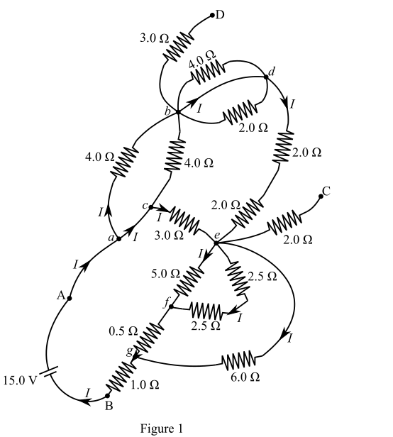
There are seven nodes a, b, c, d, e, f, and g as shown in Figure 1.
The nodes a and c are shorted, and thus there is no resistance between a and c.
Calculate the equivalent resistance between nodes a and b.
The
Recall the expression for equivalent resistance in a parallel connection.
Here,
Substitute
The equivalent resistance between nodes b and d is zero because nodes b and d are shorted. The
The equivalent resistance between nodes b and d is not in the circuit, because terminal d is open-circuited.
The
Calculate the equivalent resistance between nodes d and e.
Recall the expression for the equivalent resistance in a series connection.
Here,
Substitute
The equivalent resistance between nodes e and c is not in the circuit, because terminal c is open-circuited.
The
Calculate
Recall the expression for the equivalent resistance in a series connection.
Here,
Substitute
Now the
Calculate the equivalent resistance between nodes e and f.
Recall the expression for equivalent resistance in a parallel connection.
Here,
Substitute
Now the
Calculate
Recall the expression for the equivalent resistance in a series connection.
Here,
Substitute
Substitute
Now the
Calculate the equivalent resistance between nodes e and g.
Recall the expression for equivalent resistance in a parallel connection.
Here,
Substitute
Figure 2 shows the reduced form of Figure 1.
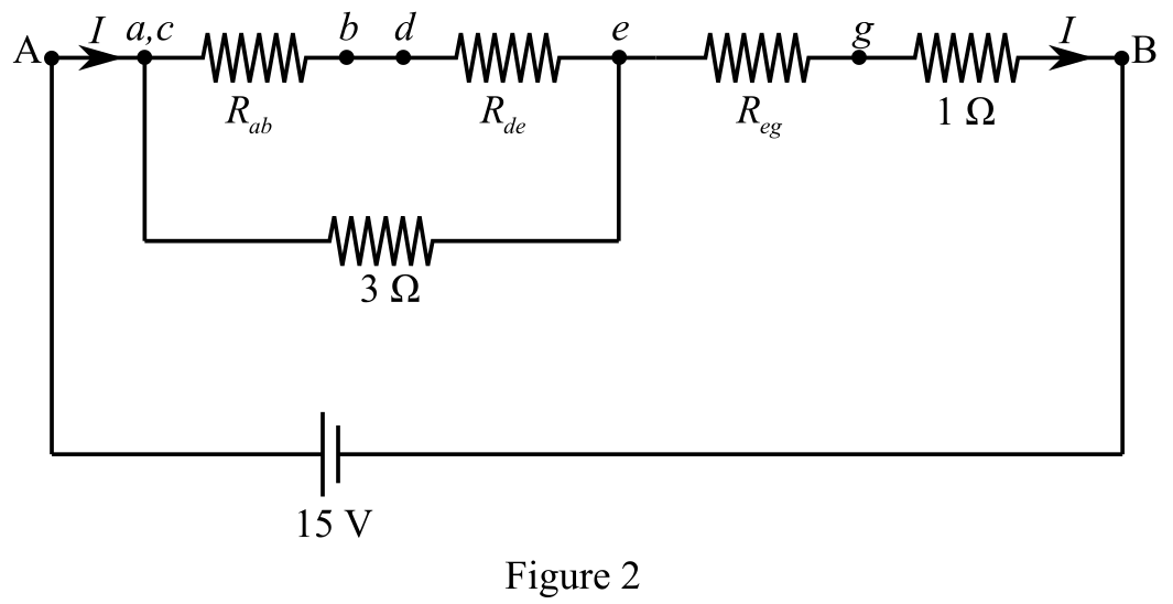
Calculate the equivalent resistance between nodes a and e.
Nodes b and d are shorted.
The resistor
Calculate
Recall the expression for the equivalent resistance in a series connection.
Here,
Substitute
Again substitute
Now, the
Calculate the equivalent resistance between nodes a and e.
Recall the expression for equivalent resistance in a parallel connection.
Here,
Substitute
Figure 3 shows the reduced form of Figure 2.
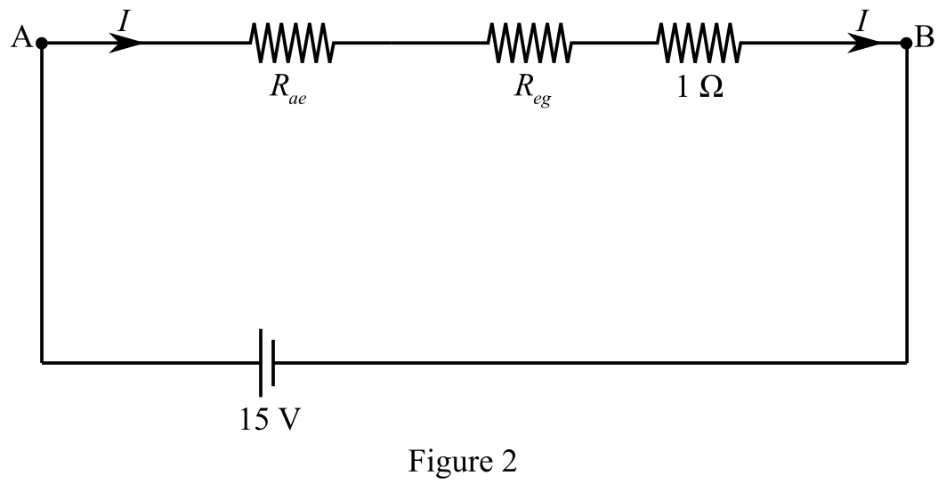
Calculate the equivalent resistance between terminals A and B.
The resistances
Recall the expression for the equivalent resistance in a series connection.
Here,
Substitute
Substitute
Conclusion:
Therefore, the equivalent resistance between terminals A and B is
(b)
The amount of the current flow from the
Answer to Problem 39SP
Solution:
Explanation of Solution
Given data:
Refer to Figure 3.
The power supply between terminals A and B is
The equivalent resistance between terminals A and B is
Formula used:
Write the expression for current from Ohm’s law.
Here,
Explanation:
Calculate the amount of the current flow through the
The current flow through the
Recall the expression for current from Ohm’s law.
Here,
Substitute
Conclusion:
Therefore, the current flow through the
(c)
The net power dissipated by all resistors in the circuit given in Fig. 28-22.
Answer to Problem 39SP
Solution:
Explanation of Solution
Given data:
The power supply between terminals A and B is
The total current flow between terminals A and B is
Formula used:
Write the expression for power.
Here,
The net power dissipated by all resistors in the given circuit is equal to the total power delivered by the power supply because the power supply does not have any internal resistance.
Explanation:
Calculate the total power delivered by the power supply.
Recall the expression for power.
Here,
Substitute
The total power delivered is equal to the power dissipated by all the resistors.
Conclusion:
Therefore, the power dissipated by all resistors in the given circuit is
Want to see more full solutions like this?
Chapter 28 Solutions
Schaum's Outline of College Physics, Twelfth Edition (Schaum's Outlines)


- 10. Consider an RC circuit with e = 12.0 V, R = 195 Q, and C = 45.7 µF. Find (a) the time constant for %3D the circuit, (b) the maximum charge on the capacitor, and (c) the initial current in the circuit. Chap 21_#77arrow_forwardTwo different electrical devices have the same power consumption, but one is meant to be operated on 120-V AC and the other on 240-V AC. (a) What is the ratio of their resistances? (b) What is the ratio of their currents? (c) Assuming its resistance is unaffected, by what factor will the power increase if a 120-V AC device is connected to 240-V AC?arrow_forward(b) For the dc network shown in Figure Q3 (b), calculate the following: i. The indicated voltage V1 and V2 ii. The power dissipated in the 3 kQ and 20-kO resistors i. The power supplied by the current source. iv. The current through 1 kQ and 3 kQ 1 kQ 3 ΚΩ (4)30 mA 5 k2 20 kΩ Figure Q3 (b) ww wwarrow_forward
- (6) Suppose two electrical resistors with resistance R₁> 0 and R₂ > 0 are wired in parallel in a circuit: R₁ ww R₂ 1 1 1 + Then the combined resistance R, measured in ohms (2), is given by R R₁ R₂ ƏR ƏR (a) Find and after solving for R (e.g., R= ...). ƏR₁ ƏR₂ (b) Describe how an increase in R₁ with R₂ held constant will change R. (Will R increase or decrease?) (c) Describe how a decrease in R₂ with R₁ held constant will hange R. (Will R increase or decrease?)arrow_forward(69%) Problem 10: In the figure, these three resistors are counected to a voltage source so that Ry = 5.5 a and R3 = 8.5 2 are in parallel with one anotber and that combination is in series with R = 0.75 0. R z = ? 12.0 V R R3 2 * 50% Part (a) Calculate the power being dissipated by the third resistor R3. in watts. Grade Summary P;- Deductions Potentiul 100% Late Work % 75%% sin() cos() lani) 7 OME Late Putential cotan() asin) acos() E 4 5 6 Submissions sinh) 23 Attempts remaining: 996 (0% per attermpt) detailed view atan() acotan() cosh() tanh() cotanh) END O Degrees C Radians 0% VO DACKSACE CLBAR 1 2 0% 0% Hint I give up Suhmit Feedbackarrow_forward(a) Calculate the capacitance needed to get an RC time constant of 1.00×10³ s with a 0.100-Ω resistor. (b) What is unreasonable about this result? (c) Which assumptions are responsible?arrow_forward
- 95 In Fig. 27-79, E, = 6.00 V, = 12.0 V, R = 100 0, R, = 200 N, and R, = 300 N. One point of the circuit is grounded (V = the (a) size and (b) direction (up or down) of the current through resistance 1, the (c) size and (d) direction (left or right) of the current through resistance 2, and the (e) size and (f) direction of the current through resistance 3? (g) What is the electric potential at point A? 0), What arearrow_forwardWhat is the smallest capacitor needed in a computer power supply in order to produce at least 3.75 V for 0.31 seconds after the power goes off? Assume that the resistance of all the components of the computer motherboard is 6 Ohms and that the capacitor and motherboard are powered with a 5-Volt power supply.arrow_forwardA 1 Ω resistor and a 4 Ω resistor are connected in parallel. The combination is connected in series with a 5.2 Ω resistor and a 24 V supply. (iii) Calculate the voltage (in V) across the 1 Ω resistorarrow_forward
- 25) A 12.0-V emf automobile battery has a terminal voltage of 16.0 V when being charged by a current of 10.0 A. (a) What is the battery’s internal resistance? (b) What power is dissipated inside the battery? (c) At what rate (in °C/min) will its temperature increase if its mass is 20.0 kg and it has a specific heat of 0.300kcal/kg·°C, assuming no heat escapes? Please show all work using this. (Actual values, equations, and drawings)arrow_forwardA coffee maker is rated at 1.20 kW, a toaster at 1.10 kW, and a waffle maker at 1.40 kW. The three appliances are connected in parallel to a common 120 V household circuit. (d) What total current is delivered to the appliances when all are operating simultaneously?arrow_forwardVII (a) In the given circuit, determine (a) the equivalent resistance and (b) the voltage across each resistor. 830) Ω Vo=c C 12.0 V (b) The RC circuit of figure given below has R = 4.7K and C= 2µF. The capacitor is at a voltage V₁ at t = 0, when the switch is closed. How long does it take the capacitor to discharge to 40 % of its initial voltage? S 680 Ω R 470 92arrow_forward
 Principles of Physics: A Calculus-Based TextPhysicsISBN:9781133104261Author:Raymond A. Serway, John W. JewettPublisher:Cengage Learning