Concept explainers
Videos
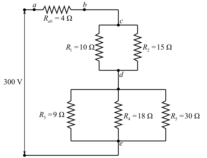
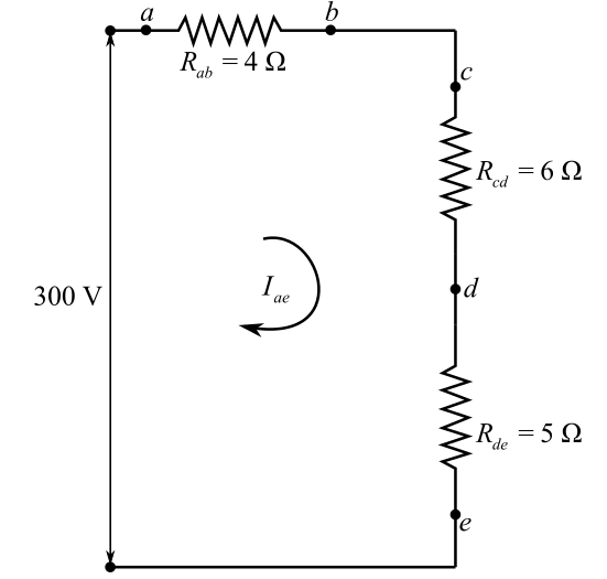
For the circuit shown in Fig. 28-14, find (a) its equivalent resistance; (b) the current drawn from the power source; (c) the potential differences across ab, cd, and de; (d) the current in each resistor.
![Chapter 28, Problem 31SP, 28.31 [II] For the circuit shown in Fig. 28-14, find (a) its equivalent resistance; (b) the current](https://content.bartleby.com/tbms-images/9781259587399/Chapter-28/images/87399-28-31sp-question-digital_image79.png)
Fig. 28-14
(a)
The net resistance across the circuit provided in the figure 28-14 in the textbook.
Answer to Problem 31SP
Solution:
Explanation of Solution
Given data:
The resistances
The resistances
The resistance across circuit
The voltage across the terminal
Formula used:
The expression for the equivalent resistance in series is written as
Here,
The expression for the equivalent resistance in parallel is written as
Here,
Explanation:
Refer to the fig. 28-14from the textbook.
Draw the circuit diagram:
Since, the resistance
Write the expression for the resistances across
Here,
Substitute
Solve for
Modify the above drawn circuit diagram by using
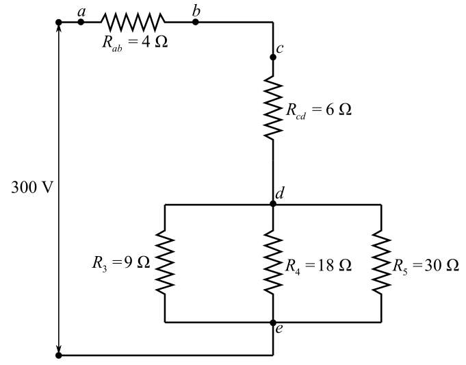
Understand that the resistors
Here,
Substitute
Here,
Redraw the modified circuit diagram by using the calculated equivalent resistances across the nodes:
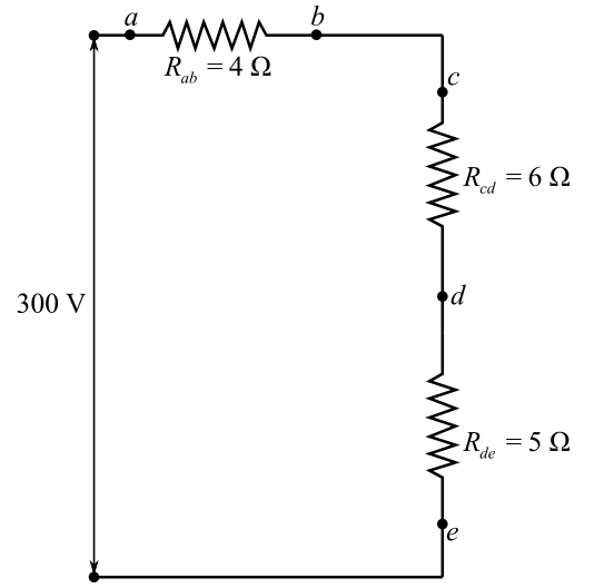
Since, all the resisters in the above diagram arein series combination.
Write the expression for the total resistance of the equivalent resistances across
Here,
Substitute
Conclusion:
The net resistance across the point
(b)
The current drawn from the source if the voltage across the circuit is
Answer to Problem 31SP
Solution:
Explanation of Solution
Given data:
Voltage across the circuit is
Formula used:
The expression for theOhm`s law if net current
Explanation:
Redraw the equivalent circuit diagram:
In the above diagram,
Rewrite the expression of the Ohm`s law for the net current across circuit
Here,
Rearrange for
Here,
Substitute
Conclusion:
Therefore, the current drawn from the source is
(c)
The voltage difference across circuits
Answer to Problem 31SP
Solution:
Explanation of Solution
Given data:
The current across
The resistances of the resistor are provided in the figure as
Formula used:
The expression for the net Voltage
Explanation:
The current in the series combination of circuits
Write the expression for the voltage across circuit
Here,
Substitute
Write the expression for the voltage across circuit
Here,
Substitute
Write the expression for the voltage across circuit
Here,
Substitute
Conclusion:
The voltages across circuits
(d)
The current across each resistor if the voltage and current across each circuit are known.
Answer to Problem 31SP
Solution:
Explanation of Solution
Given data:
The voltage across the circuit
The voltage across the circuit
The voltage across the circuit
The current across the circuit
Formula used:
The expression for the net voltage
Explanation:
In this, wewill use the fact that voltage across each resistor in a parallel combination of resistors remains same.
According to the Ohm’s law, the current across the
Rearrange for
Here
Substitute
The voltage across the parallel combination of resistance
Write the expression for the current across
Rearrange for
Here,
Substitute
Write the expression for the current across
Rearrange for
Here,
Substitute
The voltage across the parallel combination of resistors
Write the expression for the current across
Rearrange for
Here,
Substitute
Write the expression for the current across
Rearrange for
Here,
Substitute
Write the expression for the current across
Rearrange for
Here,
Substitute
Conclusion:
The current across the
Want to see more full solutions like this?
Chapter 28 Solutions
Schaum's Outline of College Physics, Twelfth Edition (Schaum's Outlines)


- A resistor made of Nichrome wire is used in an application where its resistance cannot change more than 1.00% from its value at 20.0oC . Over what temperature range can it be used?arrow_forwardOf what material is a resistor made if its resistance is 40.0% greater at 100ºC than at 20.0ºC ?arrow_forwardGiven the resistances of 1 Ω, 2 Ω, 3 Ω, how will be combine them to get an equivalent resistance of (i) (11/3) Ω (ii) (11/5) Ω, (iii) 6Ω, (iv) (6/11) Ω?arrow_forward
- A resistor made of nichrome wire is used in an application where its resistance cannot change more than 1.00% from its value at 20.0 °C . Over what temperature range can it be used?arrow_forwardAt room temperature (27.0 °C) the resistance of a heating element is 100 Ω. What is the temperature of the element if the resistance is found to be 117 Ω, given that the temperature coefficient of the material of the resistor is 1.70 × 10⁻⁴ °C-1arrow_forwardIs it possible to connect a group of resistors of value R in such a waythat the equivalent resistance is less than R? If so, give a specificexamplearrow_forward
- The power dissipated in a resistor is given by P = V 2 / R , which means power decreases if resistance increases. Yet this power is also given by P = I 2R , which means power increases if resistance increases. Explain why there is no contradiction here.arrow_forwardYou connect a 10.0 MΩ resistor in series with a 3.20 mFcapacitor and a battery with emf 9.00 V. Before you close the switchat t = 0 to complete the circuit, the capacitor is uncharged. Find the fraction of the initial current present at t = 18.0 sarrow_forwardHow many different resistance valuescan be created by combining three unequal resistors? (Don’t count possibilities in which not allthe resistors are used, i.e., ones in which there iszero current in one or more of them.)arrow_forward
- The temperature coefficient of a certain conducting material is 4.78 × 10⁻³ (°C)-1. (a) At what temperature would the resistance be 3 times the resistance at 20.0°C? (Use 20.0°C as the reference point in ρ-ρ0=ρ0α(T-T0).) (b) Does this temperature hold for all copper conductors, regardless of shape or size?arrow_forwardPerson with body resistance between his hands of 10.0 kΩ accidentally grasps the terminals of a 20.0-kV power supply. (Do NOT do this!) If the power supply is to be made safe by increasing its internal resistance, what should the internal resistance be for the maximum current in this situation to be 1.00 mA or less?arrow_forwardWhen two unknown resistors are connected in series with abattery, the battery delivers 225 W and carries a total currentof 5.00 A. For the same total current, 50.0 W is delivered whenthe resistors are connected in parallel. Determine the value ofeach resistor.arrow_forward
