
Concept explainers
Videos
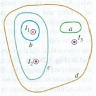
Figure E28.40 shows, in cross section, several conductors that carry currents through the plane of the figure. The currents have the magnitudes I1 = 4.0 A, I2 = 6.0 A. and I3 = 2.0 A, and the directions shown. Four paths, labeled a through d, are shown. What is the line integral
Figure E28.40

Trending nowThis is a popular solution!

Learn your wayIncludes step-by-step video

Chapter 28 Solutions
University Physics with Modern Physics (14th Edition)
Additional Science Textbook Solutions
Essential University Physics: Volume 2 (3rd Edition)
Modern Physics
Conceptual Physical Science (6th Edition)
College Physics (10th Edition)
College Physics: A Strategic Approach (3rd Edition)


- Each of the eight conductors in the figure carries 3.15 A of current into or out of the page. Two paths are indicated for the line integral B. ds. What is the value of the integral for (a) path 1 and (b) path 2?arrow_forwardA conducting rod with a circular cross-section (this rod is a cylinder) has a radius of 1o mm and is 2 metres long. The rod is made of aluminum, so its conductivity is 3.6 x 10' s/m. A potential difference (voltage) is applied at both ends of this rod and the current is I= 90 A. That's a lot of current! a. What is the resistance of the rod, when measured from one end to the other? b. Calculate the current density in the rod along its length. . Determine the electric field amplitude at all locations within the rod. d. What is the electric potential difference between the two ends of the rod.arrow_forwardA (1.91x10^2)-mA current is used to charge up a parallel plate capacitor. A large square piece of paper is placed between the plates and parallel to them so it sticks out on all sides. What is the value of the integral P B. ds around the perimeter of the paper? Express your result in T.m with three significant figures.arrow_forward
- The figure below is a cross-sectional view of a coaxial cable. The center conductor is surrounded by a rubber layer, an outer conductor, and another rubber layer. In a particular application, the current in the inner conductor is I1 = 1.12 A out of the page and the current in the outer conductor is I2 = 3.04 A into the page. Assuming the distance d = 1.00 mm, answer the following. PS:Please make sure your answer is in µTarrow_forwardAn electron is travelling at 100.0 km/s parallel to a long straight horizontal conductor a distance of 3.00 cm from the conductor. A current of 12.0 A runs through the wire as the electron travels parallel to it, in the same direction as the electron’s velocity. Find the strength of the external electric field that will prevent the electron from deviating from its original path. Express your answer in V/marrow_forward33. Parts (a) through (e) of this problem should be done by inspection-that is, mentally. The intent is to obtain an approximate solution without a lengthy series of calcula- tions. For the network in Fig. 102: a. What is the approximate value of I1, considering the magnitude of the parallel elements? b. What is the ratio I¡/I2? Based on the result of part (a), what is an approximate value of 12? c. What is the ratio I/I3? Based on the result, what is an approximate value of I3? d. What is the ratio I/I4? Based on the result, what is an approximate value of I4? e. What is the effect of the parallel 100 kN resistor on the above calculations? How much smaller will the current I4 be than the current I¡? f. Calculate the current through the 1 2 resistor using the current divider rule. How does it compare to the result of part (a)? g. Calculate the current through the 10 2 resistor. How does it compare to the result of part (b)? h. Calculate the current through the 1 kn resistor. How does…arrow_forward
- Part 7 of 8 - Analyze Now the friends try a homework problem. A capacitor is constructed with two parallel metal plates each with an area of 0.56 m² and separated by d = 0.80 cm. The two plates are connected to a 5.0-volt battery. The current continues until a charge of magnitude Q accumulates on each of the oppositely charged plates. Find the electric field in the region between the two plates. 625 ✓ V/m Find the charge Q. 1.97e-10 X C Find the capacitance of the parallel plates. x 10-6 F Submit Skip (you cannot come back)arrow_forwardThe capacitor in the circuit shown below is initially uncharged. The switch is closed at t = 0 s. AVbattery = 30 V, C = 3.0 F, and R=2.0 Q. At sometime after the switch is closed, the current in the circuit is measured to be 3.1 A. What is the charge on the capacitor at this time, in Coulomb? Your answer needs to have 2 significant figures, including the negative sign in your answer if needed. Do not include the positive sign if the answer is positive. No unit is needed in your answer, it is already given in the question statement.arrow_forwardConsider a coaxial cable as shown in the figure. The cable consists of a solid inner conductor of radius ri = 0.2 cm that is surrounded by a cylindrical tube of inner radius r2 0.8 cm and outer radius r3 = 1.7 cm. The conductors carry equal and opposite currents I = 1 A but the current density varies linearly with the distance from the center for the inner conductor (j1 = C1r) while it is distributed uniformly for the outer conductor. Determine the magnetic field (in units of µT (microtesla)) at a distance r = 1.5 cm from the axis. (Ho = 4n x 10 7N/A² and a = 3.14) Answer:arrow_forward
- The capacitor in the circuit shown below is initially uncharged. The switch is closed at t=0 s. AVbattery = 30 V, C = 3.0 F, and R = 2.0 Q. At sometime after the switch is closed, the current in the circuit is measured to be 5.9 A. What is the charge on the capacitor at this time, in Coulomb? Your answer needs to have 2 significant figures, including the negative sign in your answer if needed. Do not include the positive sign if the answer is positive. No unit is needed in your answer, it is already given in the question statement. CHarrow_forwardA coaxial cable consists of a solid center conducting wire and an outer coaxial cylindrical conductor. The space between the conductors and the outer insulation are made of a good insulating material e.g. neoprene. The figure below shows a cross section of such a cable. The current in the center wire is 2.47 A out of the page and the current in the outer conductor is 2.98 A into the page. If the distance a is 2.00 mm, determine the following. (a) the magnitude and direction of the magnetic field at the point P1. (b) the magnitude and direction of the magnetic field at the point P2arrow_forwardThe figure shows, in cross section, several conductors that carry currents through the plane of the figure. The currents have the magnitudes I1= 4.0 A, I2= 6.5 A, and I3= 1.9 A, and the directions shown. Four paths, labeled a through d, are shown. (Figure 1) Part A What is the line integral ∮B⃗⋅dl⃗ for the path a? The integral involves going around the path in the counterclockwise direction. Part B What is the line integral ∮B⃗⋅dl⃗ for the path b? The integral involves going around the path in the counterclockwise direction. Part C What is the line integral ∮B⃗⋅dl⃗ for the path c? The integral involves going around the path in the counterclockwise direction. Part D What is the line integral ∮B⃗⋅dl⃗ for the path d? The integral involves going around the path in the counterclockwise direction.arrow_forward

 College PhysicsPhysicsISBN:9781938168000Author:Paul Peter Urone, Roger HinrichsPublisher:OpenStax College
 Physics for Scientists and Engineers: Foundations...PhysicsISBN:9781133939146Author:Katz, Debora M.Publisher:Cengage Learning