
Videos
The circuit in Figure P27.85 shows four capacitors connected to a battery. The switch S is initially open, and all capacitors have reached their final charge. The capacitances are C1 = 6.00 μF, C2 = 12.00 μF, C3 = 8.00 μF, and C4 = 4.00 μF. a. Find the potential difference across each capacitor and the charge stored in each. b. The switch is now closed. What is the new final potential difference across each capacitor and the new charge stored in each?
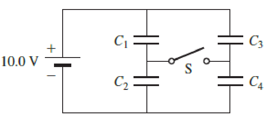
Figure P27.85
(a)
The potential difference across the capacitors and the charge stores in each capacitor.
Answer to Problem 85PQ
The charge stored in
The potential difference across the capacitors
Explanation of Solution
The circuit diagram,

Since, the capacitors
Write the expression to find the equivalent capacitance on
Here,
Substitute
Write the expression to find the charges on
Here,
Substitute
Write the expression to find the equivalent capacitance on
Here,
Substitute
Write the expression to find the charges on
Here,
Substitute
Write the equation to find the voltage across the capacitor.
Conclusion:
Substitute
Substitute
Substitute
Substitute
Therefore, the charge stored in
The potential difference across the capacitors
(b)
The potential difference across the capacitors and the charge stores in each capacitor when the switch is closed.
Answer to Problem 85PQ
The charge stored in
The potential difference across the capacitors
Explanation of Solution
The circuit diagram,
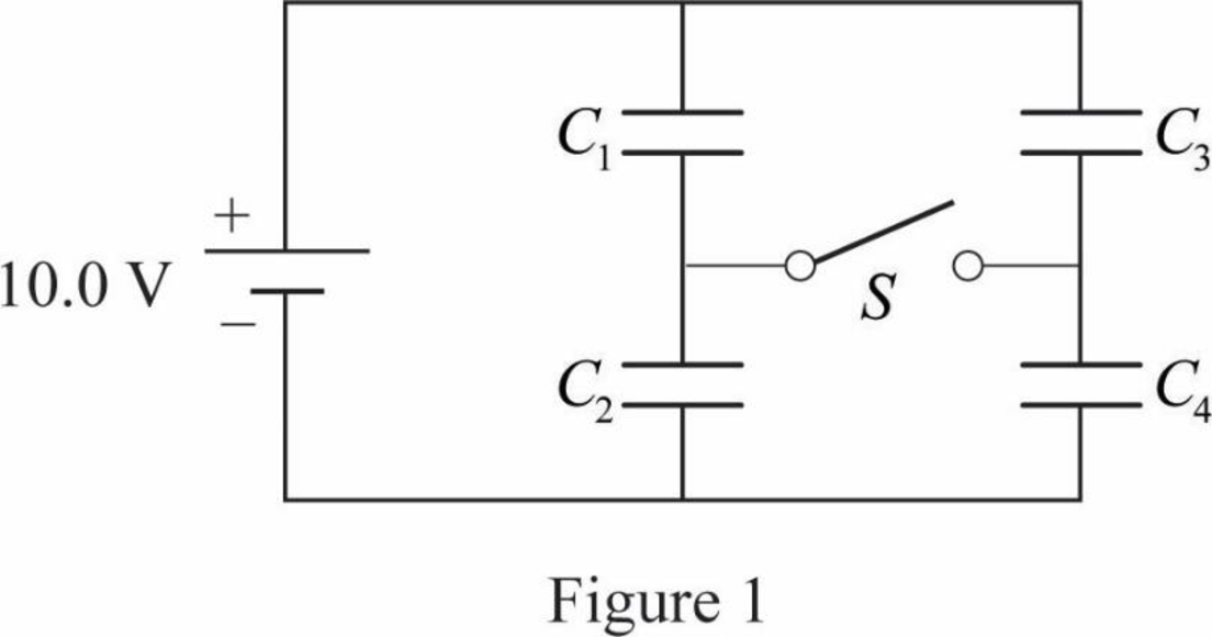
When the switch is closed, the capacitors
Write the expression to find the equivalent capacitance on
Here,
Substitute
Write the expression to find the equivalent capacitance on
Here,
Substitute
Write the expression to find the equivalent capacitance of the circuit.
Here,
Substitute
Write the expression to find the charges on the capacitors.
Here,
Substitute
Write the equation to find the voltage across the capacitor.
Conclusion:
Substitute
Substitute
Therefore, the charge stored in
The potential difference across the capacitors
Want to see more full solutions like this?
Chapter 27 Solutions
Physics for Scientists and Engineers: Foundations and Connections


- A Pairs of parallel wires or coaxial cables are two conductors separated by an insulator, so they have a capacitance. For a given cable, the capacitance is independent of the length if the cable is very long. A typical circuit model of a cable is shown in Figure P27.87. It is called a lumped-parameter model and represents how a unit length of the cable behaves. Find the equivalent capacitance of a. one unit length (Fig. P27.87A), b. two unit lengths (Fig. P27.87B), and c. an infinite number of unit lengths (Fig. P27.87C). Hint: For the infinite number of units, adding one more unit at the beginning does not change the equivalent capacitance.arrow_forwardThe circuit in Figure P21.59 has been connected for a long time. (a) What is the potential difference across the capacitor? (b) If the battery is disconnected from the circuit, over what time interval does the capacitor discharge to one-tenth its initial voltage?arrow_forward(a) Determine the equilibrium charge on the capacitor in the circuit of Figure P27.46 as a function of R. (b) Evaluate the charge when R = 10.0 . (c) Can the charge on the capacitor be zero? If so, for what value of R? (d) What is the maximum possible magnitude of the charge on the capacitor? For what value of R is it achieved? (c) Is it experimentally meaningful to take R = ? Explain your answer. If so, what charge magnitude does it imply? Figure P27.46arrow_forward
- Figure P27.75 shows four capacitors with CA = 4.00 F, CB = 8.00 F. CC = 6.00 F. and CD = 5.00 F connected across points a and b, which have potential difference Vab = 12.0 V. a. What is the equivalent capacitance of the four capacitors? b. What is the charge on each of the four capacitors?arrow_forwardTwo 1.5-V batteries are required in a flashlight. a. If the batteries are connected as shown in configuration 1 in Figure P27.18, what is the potential difference between points A and B? b. If, instead, the batteries are connected as shown in configuration 2, what is the potential difference between points A and B? c. Use your answers to figure out why a flashlight with two good batteries may not light up. FIGURE P27.18arrow_forwardA battery is used to charge a capacitor through a resistor as shown in Figure P27.44. Show that half the energy supplied by the battery appears as internal energy in the resistor and half is stored in the capacitor. Figure P27.44arrow_forward
- The circuit shown in Figure P28.78 is set up in the laboratory to measure an unknown capacitance C in series with a resistance R = 10.0 M powered by a battery whose emf is 6.19 V. The data given in the table are the measured voltages across the capacitor as a function of lime, where t = 0 represents the instant at which the switch is thrown to position b. (a) Construct a graph of In (/v) versus I and perform a linear least-squares fit to the data, (b) From the slope of your graph, obtain a value for the time constant of the circuit and a value for the capacitance. v(V) t(s) In (/v) 6.19 0 5.56 4.87 4.93 11.1 4.34 19.4 3.72 30.8 3.09 46.6 2.47 67.3 1.83 102.2arrow_forwardAn oceanographer is studying how the ion concentration in seawater depends on depth. She makes a measurement by lowering into the water a pair of concentric metallic cylinders (Fig. P21.66) at the end of a cable and taking data to determine the resistance between these electrodes as a function of depth. The water between the two cylinders forms a cylindrical shell of inner radius ra, outer radius rb, and length L much larger than rb. The scientist applies a potential difference V between the inner and outer surfaces, producing an outward radial current I. Let represent the resistivity of the water. (a) Find the resistance of the water between the cylinders in terms of L, , ra, an rb. (b) Express the resistivity of the water in terms of the measured quantities L, ra, rb, V, and I. Figure P21.66arrow_forward(a) Calculate the potential difference between points a and b in Figure P27.37 and (b) identify which point is at the higher potential. Figure P27.37arrow_forward
- A pair of capacitors with capacitances CA = 3.70 F and CB = 6.40 F are connected in a network. What is the equivalent capacitance of the pair of capacitors if they are connected a. in parallel and b. in series?arrow_forwardSuppose you need to measure the potential difference between the points in Figure P29.4. Assume the voltmeter reading is the potential difference between the two leads: V = Vred Vblack. For each of the following measurements, determine at which point you would connect the red lead and at which point you would connect the black lead: a. Vb Va. b. Vc Vb. c. Vd Vc. d. Va Vd. FIGURE P29.4 Problems 4, 5, and 6.arrow_forwardThe circuit in Figure P27.35 has been connected for several seconds. Find the current (a) in the 4.00-V battery, (b) in the 3.00- resistor, (c) in the 8.00-V battery, and (d) in the 3.00-V battery. (e) Find the charge on the capacitor. Figure P27.35arrow_forward
 Physics for Scientists and Engineers: Foundations...PhysicsISBN:9781133939146Author:Katz, Debora M.Publisher:Cengage Learning
 Physics for Scientists and Engineers with Modern ...PhysicsISBN:9781337553292Author:Raymond A. Serway, John W. JewettPublisher:Cengage Learning
 Physics for Scientists and EngineersPhysicsISBN:9781337553278Author:Raymond A. Serway, John W. JewettPublisher:Cengage Learning
 Principles of Physics: A Calculus-Based TextPhysicsISBN:9781133104261Author:Raymond A. Serway, John W. JewettPublisher:Cengage Learning
 Physics for Scientists and Engineers, Technology ...PhysicsISBN:9781305116399Author:Raymond A. Serway, John W. JewettPublisher:Cengage Learning