
University Physics (14th Edition)
14th Edition
ISBN: 9780133969290
Author: Hugh D. Young, Roger A. Freedman
Publisher: PEARSON
expand_more
expand_more
format_list_bulleted
Videos
Textbook Question
Chapter 26, Problem 26.11E
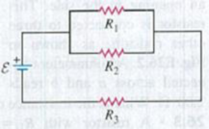
In Fig. E26.11, R1, = 3.00 Ω, R2 = 6.00 Ω, and R3= 5.00 Ω. The battery has negligible internal resistance. The current I2 through R2 is 4.00 A. (a) What are the currents I1 and I2? (b) What is the emf of the battery?
Figure E26.11
Expert Solution & Answer
Want to see the full answer?
Check out a sample textbook solution
Students have asked these similar questions
26.11 In Fig. E26.11, R₁ = 3.00, R₂ = 6.00 , and R3 =
5.00 2. The battery has negligible internal resistance. The current 1₂
through R₂ is 4.00 A. (a) What are the currents I₁ and 13? (b) What is the
emf of the battery?
Figure E26.11
R₁
R₂
www
R3
25.54. In the circuit shown in
Fig. P25.54, R is a variable resistor whose
value ranges from 0 to co, and a and b are
the terminals of a battery that has an emf
E = 15.0V and an internal resistance of
4.00 2. The ammeter and voltmeter are
idealized meters. As R varies over its full
range of values, what will be the largest
and smallest readings of (a) the voltmeter
and (b) the ammeter? (c) Sketch qualita-
tive graphs of the readings of both meters
as functions of R.
Figure P25.54
R
Five resistors with known resistances R1 = 5.00 Ω, R2 = 5.00 Ω, R3 = 7.00 Ω, R4 = 5.00 Ω, and R5 = 6.00 Ω are connected to a battery with emf = 8.00 V as shown in the figure. What are the currents in resistors R1, R2, R3, R4, and R5? What is the absolute value of the potential difference between the points P and P ′?
Chapter 26 Solutions
University Physics (14th Edition)
Ch. 26 - In which 120-V light bulb does the filament have...Ch. 26 - Two 120-V light bulbs, one 25-W and one 200-W,...Ch. 26 - You connect a number of identical light bulbs to a...Ch. 26 - In the circuit shown in Fig. Q26.4, three...Ch. 26 - If two resistors R1 and R2 (R2 R1) are connected...Ch. 26 - If two resistors R1 and R2 (R2 R1) are connected...Ch. 26 - A battery with no internal resistance is connected...Ch. 26 - A resistor consists of three identical metal...Ch. 26 - A light bulb is connected in the circuit shown in...Ch. 26 - A real battery, having nonnegligible internal...
Ch. 26 - If the battery in Discussion Question Q26.10 is...Ch. 26 - Consider the circuit shown in Fig. Q26.12. What...Ch. 26 - Is it possible to connect resistors together in a...Ch. 26 - The battery in the circuit shown in Fig. Q26.14...Ch. 26 - In a two-cell flashlight, the batteries are...Ch. 26 - Identical light bulbs A, B, and C are connected as...Ch. 26 - The emf of a flashlight battery is roughly...Ch. 26 - Will the capacitors in the circuits shown in Fig....Ch. 26 - Verify that the time constant RC has units of...Ch. 26 - For very large resistances it is easy to construct...Ch. 26 - When a capacitor, battery, and resistor are...Ch. 26 - A uniform wire of resistance R is cut into three...Ch. 26 - A machine part has a resistor X protruding from an...Ch. 26 - A resistor with R1 = 25.0 is connected to a...Ch. 26 - A 42- resistor and a 20- resistor are connected in...Ch. 26 - A triangular array of resistors is shown in Fig....Ch. 26 - For the circuit shown in Fig. E26.6 both meters...Ch. 26 - For the circuit shown in Fig. E26.7 find the...Ch. 26 - Three resistors having resistances of 1.60 , 2.40...Ch. 26 - Now the three resistors of Exercise 26.8 are...Ch. 26 - Power Rating of a Resistor. The power rating of a...Ch. 26 - In Fig. E26.11, R1, = 3.00 , R2 = 6.00 , and R3=...Ch. 26 - In Fig. E26.11 the battery has emf 35.0 V and...Ch. 26 - Compute the equivalent resistance of the network...Ch. 26 - Compute the equivalent resistance of the network...Ch. 26 - In the circuit of Fig. E26.15, each resistor...Ch. 26 - Consider the circuit shown in Fig. E26.16. The...Ch. 26 - In the circuit shown in Fig. E26.17, the voltage...Ch. 26 - In the circuit shown in Fig. E26.18, = 36.0 V,...Ch. 26 - CP In the circuit in Fig. E26.19, a 20.0- resistor...Ch. 26 - In the circuit shown in Fig. E26.20, the rate at...Ch. 26 - Light Bulbs in Series and in Parallel. Two light...Ch. 26 - Light Bulbs in Series. A 60-W, 120-V light bulb...Ch. 26 - In the circuit shown in Fig. E26.23, ammeter A1...Ch. 26 - The batteries shown in the circuit in Fig. E26.24...Ch. 26 - In the circuit shown in Fig. E26.25 find (a) the...Ch. 26 - Find the emfs 1 and 2 in the circuit of Fig....Ch. 26 - In the circuit shown in Fig. E26.27, find (a) the...Ch. 26 - In the circuit shown in Fig. E26.28, find (a) the...Ch. 26 - The 10.00-V battery in Fig. E26.28 is removed from...Ch. 26 - The 5.00-V battery in Fig. E26.28 is removed from...Ch. 26 - In the circuit shown in Fig. E26.31 the batteries...Ch. 26 - In the circuit shown in Fig. E26.32 both batteries...Ch. 26 - In the circuit shown in Fig. E26.33 all meters are...Ch. 26 - In the circuit shown in Fig. E26.34, the 6.0-...Ch. 26 - The resistance of a galvanometer coil is 25.0 ,...Ch. 26 - The resistance of the coil of a pivoted coil...Ch. 26 - A circuit consists of a series combination of...Ch. 26 - A galvanometer having a resistance of 25.0 has a...Ch. 26 - A capacitor is charged to a potential of 12.0 V...Ch. 26 - You connect a battery, resistor, and capacitor as...Ch. 26 - A 4.60-F capacitor that is initially uncharged is...Ch. 26 - You connect a battery, resistor, and capacitor as...Ch. 26 - CP In the circuit shown in Fig. E26.43 both...Ch. 26 - A 12.4-F capacitor is connected through a 0.895-M...Ch. 26 - An emf source with = 120 V, a resistor with R =...Ch. 26 - A resistor and a capacitor are connected in series...Ch. 26 - CP In the circuit shown in Fig. E26.47 each...Ch. 26 - A 1.50-F capacitor is charging through a 12.0-...Ch. 26 - In the circuit in Fig. E26.49 the capacitors are...Ch. 26 - A 12.0-F capacitor is charged to a potential of...Ch. 26 - In the circuit shown in Fig. E26.51, C = 5.90 F, ...Ch. 26 - Prob. 26.52ECh. 26 - A 1500-W electric beater is plugged into the...Ch. 26 - In Fig. P26.54, the battery has negligible...Ch. 26 - The two identical light bulbs in Example 26.2...Ch. 26 - Each of the three resistors in Fig. P26.56 has a...Ch. 26 - (a) Find the potential of point a with respect to...Ch. 26 - CP For the circuit shown in Fig. P26.58 a 20.0-...Ch. 26 - Calculate the three currents I1, I2, and I3...Ch. 26 - What must the emf in Fig. P26.60 be in order for...Ch. 26 - Find the current through each of the three...Ch. 26 - (a) Find the current through the battery and each...Ch. 26 - Consider the circuit shown in Fig. P26.63. (a)...Ch. 26 - In the circuit shown in Fig. P26.64, = 24.0 V,...Ch. 26 - In the circuit shown in Fig. P26.65, the current...Ch. 26 - In the circuit shown in Fig. P26.66 all the...Ch. 26 - Figure P26.67 employs a convention often used in...Ch. 26 - Three identical resistors are connected in series....Ch. 26 - A resistor R1 consumes electrical power P1 when...Ch. 26 - The capacitor in Fig. F26.70 is initially...Ch. 26 - A 2.00-F capacitor that is initially uncharged is...Ch. 26 - A 6.00-F capacitor that is initially uncharged is...Ch. 26 - Point a in Fig. P26.73 is maintained at a constant...Ch. 26 - The Wheatstone Bridge. The circuit shown in Fig....Ch. 26 - (See Problem 26.67.) (a) What is the potential of...Ch. 26 - A 2.36-F capacitor that is initially uncharged is...Ch. 26 - A 224- resistor and a 589- resistor are connected...Ch. 26 - A resistor with R = 850 is connected to the...Ch. 26 - A capacitor that is initially uncharged is...Ch. 26 - DATA You set up the circuit shown in Fig. 26.22a,...Ch. 26 - DATA You set up the circuit shown in Fig. 26.20....Ch. 26 - DATA The electronics supply company where you work...Ch. 26 - An Infinite Network. As shown in Fig. P26.83, a...Ch. 26 - Suppose a resistor R lies along each edge of a...Ch. 26 - BIO Attenuator Chains and Axons. The infinite...Ch. 26 - Assume that a typical open ion channel spanning an...Ch. 26 - In a simple model of an axon conducting a nerve...Ch. 26 - Cell membranes across a wide variety of organisms...
Additional Science Textbook Solutions
Find more solutions based on key concepts
4. Accuracy is
the same as precision.
the smallest unit with which a measurement is made.
the number of signifi...
Applied Physics (11th Edition)
14. (II) The maximum gauge pressure in a hydraulic lift is 17.0 atm. What is the largest-size vehicle (kg) it c...
Physics: Principles with Applications
Imagine describing the cosmic calendar to a friend. In your own words, give your friend a feel for how the huma...
Life in the Universe (4th Edition)
8. A 1000 kg car pushes a 2000 kg truck that has a dead battery. When the driver steps on the accelerator, the ...
Physics for Scientists and Engineers: A Strategic Approach, Vol. 1 (Chs 1-21) (4th Edition)
Using the definitions in Eqs. 1.1 and 1.4, and appropriate diagrams, show that the dot product and cross produc...
Introduction to Electrodynamics
81. Why does the Moon appear yellowish when it is low in the sky?
Conceptual Physical Science (6th Edition)
Knowledge Booster


Learn more about
Need a deep-dive on the concept behind this application? Look no further. Learn more about this topic, physics and related others by exploring similar questions and additional content below.Similar questions
- A 12.0-V emf automobile battery has a terminal voltage of 16.0 V when being charged by a current of 10.0 A. (a) What is the battery’s internal resistance? (b) What power is dissipated inside the battery? (c) At what rate (in °C/min ) will its temperature increase if its mass is 20.0 kg and it has a specific heat of 0.300 kcal/kg • °C, assuming no heat escapes?arrow_forwardIn (Figure 1), R1R1R_1 = 3.00 ΩΩ, R2R2R_2 = 7.00 ΩΩ, and R3R3R_3 = 4.00 ΩΩ. The battery has negligible internal resistance. The current I2I2 through R2R2 is 3.00 A . What is the emf of the battery? Express your answer with the appropriate units.arrow_forwardChapter 27, Problem 033 GO In the figure the current in resistance 6 is i6 = 1.47 A and the resistances are R₁ = R₂ = R3 = 1.75 2, R4 = 15.0, R5 = 8.83 What is the emf of the ideal battery? 66 E R₁ R₂ R₂ FWM T 8 FWM 8 www R R₁ Chapter 27, Problem 039 GO In the figure two batteries of emf E = 11.0 V and internal resistance r = 0.306 2 are connected in parallel across a resistance R. (a) For what value of R is the dissipation rate in the resistor a maximum? (b) What is that maximum? , and R6 = 3.55 9. 2. www R io Ro 16arrow_forward
- Your answer is partially correct. In the figure the current in resistance 6 is ig = 1.44 A and the resistances are R1 = R2 = R3 = 2.49 Q, R4 = 16.2 Q, R5 = 8.420, and Ré = 3.32 Q. What is the emf of the ideal battery? R R2 R4 16 Number i 44.4 Units Varrow_forwardThe circuit in Figure P27.41 contains two resistors, R1 = 2.00 kΩ and R2 = 3.00 kΩ, and two capacitors, C1 = 2.00 μF and C2 = 3.00 μF, connected to a battery with emf ε = 120 V. If there are no charges on the capacitors before switch S is closed, determine the charges on capacitors (a) C1 and (b) C2 as functions of time, after the switch is closed.arrow_forwardA 400 µF capacitor is connected through a resistor to a battery. Find (a) the resistance R and (b) the emf of the battery if the time constant of the circuit is 0.5 s and the maximum charge on the capacitor is 0.024 C. O a. R = 1350 0, e = 80 V O b. R = 1250 0, E = 60 V O C. R = 1200 Q, e = 80 V O d. R = 1150 Q, e = 60 Varrow_forward
- Two resistors, R1 = 21 Ω and R2 = 35 Ω are connected in parallel across a battery providing voltage ΔVbat = 5.7 V. What is the current through resistor R1?arrow_forward24.0 V 4.00 A R 4.00 A Figure N 8. Consider the circuit shown in Figure b. The terminal voltage of the 24.0 V battery is 21.2 V. What is a) the internal resistance r of the battery; b) the resistance R of the circuit resistor???arrow_forwardIn the figure, three resistors are connected to R3 = 8.9 0. The current through resistor R3 is 7.25 mA. ideal emf device. The resistances are R1 = 10.4 Q, R, = 21.5 Q, and R R2 R3 (a) What is the current through the other two resistors? I = mA I2 = (b) What is the terminal potential of the emf device? Varrow_forward
- You connect a battery, resistor, and a capacitor as in figure 1, where R= 15.0 ohms and C= 5.00x10^-6 F. The switch S is closed at t=0. When the current in the circuit has magnitude 3.00 A, the charge on the capacitor is 40.0x10^-6 C. (A) what is the emf of the battery? (B) at what time t after the switch is closed is the charge on the capacitor equal to 40.0x10^-6? (C) when the current has magnitude 3.00 A, at what rate is the energy being stored in the capacitor? (D) when the current has magnitude 3.00 A, at what rate is energy being supplied by the battery?arrow_forward83 = 4.7 V. What are In the figure the resistances are R₁ = 1.202 and R₂-2.40, and the ideal batteries have emfs 81 - 1.8 V, and 82 the (a) size and (b) direction (up or down) of the current in battery 1, the (c) size and (d) direction of the current in battery 2, and the (e) size and (f) direction of the current in battery 3? (g) What is the potential difference V₁-V₁? (b) R₁ (a) Number i (c) Number (d) (e) Number (f) R₁ (g) Number R₁ Units Units Units Unitsarrow_forwardIn a heart pacemaker, a pulse is delivered to the heart 84 times per minute. The capacitor that controls this pulsing rate discharges through a resistance of 3.9 ✕ 106 Ω. One pulse is delivered every time the fully charged capacitor loses 63.2% of its original charge. What is the capacitance of the capacitor? Farrow_forward
arrow_back_ios
SEE MORE QUESTIONS
arrow_forward_ios
Recommended textbooks for you

 Physics for Scientists and Engineers: Foundations...PhysicsISBN:9781133939146Author:Katz, Debora M.Publisher:Cengage Learning
Physics for Scientists and Engineers: Foundations...
Physics
ISBN:9781133939146
Author:Katz, Debora M.
Publisher:Cengage Learning
How To Solve Any Resistors In Series and Parallel Combination Circuit Problems in Physics; Author: The Organic Chemistry Tutor;https://www.youtube.com/watch?v=eFlJy0cPbsY;License: Standard YouTube License, CC-BY