
Concept explainers
Videos
(a)
The point to which a voltmeter is connected to measure the potential difference of the voltage source in the given figure.
Answer to Problem 26CQ
Explanation of Solution
Given information:
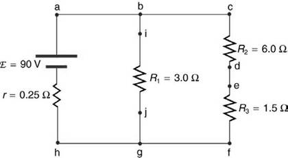
The given figure is

Introduction:
Ammeter is connected in series in the circuit to measure the current.
Voltmeter is connected in parallel in the circuit to measure the voltage.
Ammeter is a device which is used to measure the current in the circuit and is connected in series in the circuit.
It is having internal impedance whose value is zero.
Voltmeter is connected in parallel in the circuit to measure the voltage.
It is having internal impedance whose value is infinity.
In order to measure a potential difference of the voltage source the voltmeter must be connected between the points
Conclusion:
All the currents going into the junction are positive.
(b)
The point to which a voltmeter is connected to measure the potential difference across
Answer to Problem 26CQ
Explanation of Solution
Given information:
The given figure is
Introduction:
Ammeter is connected in series in the circuit to measure the current.
Voltmeter is connected in parallel in the circuit to measure the voltage.
Ammeter is a device which is used to measure the current in the circuit and is connected in series in the circuit.
It is having internal impedance whose value is zero.
Voltmeter is connected in parallel in the circuit to measure the voltage.
It is having internal impedance whose value is infinity.
In order to measure a potential difference across
Conclusion:
The point to which a voltmeter is connected to measure the potential difference across
(c)
The point to which a voltmeter is connected to measure the potential difference across
Answer to Problem 26CQ
Explanation of Solution
Given information:
The given figure is

Introduction:
Ammeter is connected in series in the circuit to measure the current.
Voltmeter is connected in parallel in the circuit to measure the voltage.
Ammeter is a device which is used to measure the current in the circuit and is connected in series in the circuit.
It is having internal impedance whose value is zero.
Voltmeter is connected in parallel in the circuit to measure the voltage.
It is having internal impedance whose value is infinity.
In order to measure a potential difference across
Conclusion:
The point to which a voltmeter is connected to measure the potential difference across
(d)
The point to which a voltmeter is connected to measure the potential difference across
Answer to Problem 26CQ
Explanation of Solution
Given information:
The given figure is

Introduction:
Ammeter is connected in series in the circuit to measure the current.
Voltmeter is connected in parallel in the circuit to measure the voltage.
Ammeter is a device which is used to measure the current in the circuit and is connected in series in the circuit.
It is having internal impedance whose value is zero.
Voltmeter is connected in parallel in the circuit to measure the voltage.
It is having internal impedance whose value is infinity.
In order to measure a potential difference across
Conclusion:
The point to which a voltmeter is connected to measure the potential difference across
(e)
The point to which a voltmeter is connected to measure the potential difference across
Answer to Problem 26CQ
Explanation of Solution
Given information:
The given figure is

Introduction:
Ammeter is connected in series in the circuit to measure the current.
Voltmeter is connected in parallel in the circuit to measure the voltage.
Ammeter is a device which is used to measure the current in the circuit and is connected in series in the circuit.
It is having internal impedance whose value is zero.
Voltmeter is connected in parallel in the circuit to measure the voltage.
It is having internal impedance whose value is infinity.
In order to measure a potential difference across
Conclusion:
The point to which a voltmeter is connected to measure the potential difference across
Want to see more full solutions like this?
Chapter 21 Solutions
COLLEGE PHYSICS


- According to UE=12C(V)2 (Eq. 27.3), a greater capacitance means more energy is stored by the capacitor, but according to UE = Q2/2C (Eq. 27.2), a greater capacitance means less energy is stored. How can both of these equations be correct?arrow_forwardFigure 21.55 shows how a bleeder resistor is used to discharge a capacitor after an electronic device is shut off allowing a person to work on the electronics with less risk of shock, (a) What is the time constant? (b) How long will it take to reduce the voltage on the capacitor to 0.250% (5% of 5%) of its full value once discharge begins? (c) If the capacitor is charged to a voltage V0through a 100-O resistance, calculate the time it takes to rise to 0.865V0(This is about two time constants.)arrow_forward(a) Find the current in each resistor of Figure P18.18 by using the rules for resistors in series and parallel. (b) Write three independent equations for the three currents using Kirchhoffs laws: one with the node rule; a second using the loop rule through the battery, the 6.0- resistor, and the 24.0- resistor; and the third using the loop rule through the 12.0- and 24.0- resistors. Solve to check the answers found in part (a). Figure Pl8.18arrow_forward
- (a) Find the current in each resistor of Figure P18.18 by using the rules for resistors in series and parallel. (b) Write three independent equations for the three currents using Kirchhoffs laws: one with the node rule; a second using the loop rule through the battery, the 6.0- resistor, and the 24.0- resistor; and the third using the loop rule through the 12.0- and 24.0- resistors. Solve to check the answers found in part (a). Figure Pl8.18arrow_forwardSuppose that the capacitance of a variable capacitor can be manually changed from 100 pF to 800 pF by turning a dial, connected to one set of plates by a shaft from 0° to 180°. With the dial set at 180° (corresponding to C — 800 pF), the capacitor is connected to a 500-V source. After charging, the capacitor is disconnected from the source, and the dial is turned to 0°. If friction is negligible, how much work is required to turn the dial from 180° to 0°?arrow_forward. If / 2.0 mA and the potential difference, VA - VB=+30 V in the circuit segment shown, determine the charge and polarity of the capacitor 50 μF 10 kQ B-m HE 40 V I O 1.5 mC, left plate is positive O'1.5 mC, right plate is positive O 0.45 mC, left plate is positive O 0.45 mC, right plate is positive Aarrow_forward
- Immediately after the switch is closed, the voltage across the 3uF capacitor is 1 MQ 45 V 3 µFarrow_forwardCap-monster maze. In the figure, all the capacitors have a capacitance of 6.0 µF, and all the batteries have an emf of 10 V. What is the charge on capacitor C? (If you can find the proper loop through this maze, you can answer the question with a few seconds of mental calculation.) H H II TIH 60 μC Ο 30 μC. Ο 120 μC 180 μC HI C I I I Larrow_forwardA potential difference of V, is applied across the system of capacitors shown at right and the capacitances are: C = 36 uF C, = 12 uF C; = 18 µF If the potential difference across capacitor C, 2. C1 Vab C2 is 96 volts then how energy is stored in capa- citor C;? (in µJoules) Сз a. 18432 b. 55296 c. 46080 d. 36864 e. 27648arrow_forward
- In the circuit shown (a) find the charge on each capacitor; (b) voltage across each capacitor and (c) voltage of the battery. Voltage acioss suF= 6V. 4uF A 3MF tcarrow_forwardQuestion 14 In its preliminary designs, the Death Star uned S00 identical parallel-plate capacitors connected in parallel to store, nd eventually releane, enough cnergy to destroy a target planet. The dutanc bue the plates is 2 mm and the Death Star's hypermatter reactor is capable of supplying a voltage of 1.0x 10 V he energy reguired to destroy an Earth-like planet is 24 10 what mad the are of cach plate bet (Aume the space between the plates is filled by vacuum) O 14x 10 O 52 x 10 m 043x 10 m OR7x10arrow_forwardCapacitor C1 = 30 microfarad and C2= 60 microfarad are connected in series. A total voltage %3D 4000 volts is applied across the combination. The total PE stored in the system is Joules 16 0.160 2000 200arrow_forward
 College PhysicsPhysicsISBN:9781938168000Author:Paul Peter Urone, Roger HinrichsPublisher:OpenStax College
 College PhysicsPhysicsISBN:9781305952300Author:Raymond A. Serway, Chris VuillePublisher:Cengage Learning
 College PhysicsPhysicsISBN:9781285737027Author:Raymond A. Serway, Chris VuillePublisher:Cengage Learning
 Physics for Scientists and Engineers: Foundations...PhysicsISBN:9781133939146Author:Katz, Debora M.Publisher:Cengage Learning