
To calculate: The thermocline depth and the flux across the interface by the use of a cubic spline fit where
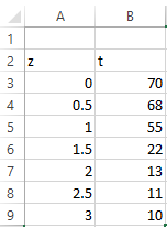
| Depth, m | 0 | 0.5 | 1.0 | 1.5 | 2.0 | 2.5 | 3.0 |
| Temperature, Celsius | 70 | 68 | 55 | 22 | 13 | 11 | 10 |
The provided graph shows the relationship between depth and temperature as,

Answer to Problem 6P
Solution:
The value of thermocline depth and the flux across the interface is
Explanation of Solution
Given Information:
The table is given as,
| Depth, m | 0 | 0.5 | 1.0 | 1.5 | 2.0 | 2.5 | 3.0 |
| Temperature, Celsius | 70 | 68 | 55 | 22 | 13 | 11 | 10 |
The provided graph shows the relationship between depth and temperature as,
Calculation:
Consider the Fourier’s law,
The value of
From the graph, this can be interpreted that curve has zero slope at
Since, the cubic spline fit is required, so this problem can be solved by the Excel VBA(Visual Basic for applications). The steps are,
Step 1. Insert the data in excel as shown below,
Step 2. Press ALT+F11 and write the code as shown below,
Step 3. Press RUN then this dialog box appears.

Step 4. Enter the value of z.

Step 5. This output will appear.
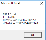
Thus, the value of
Hence, the value of thermocline depth and the flux across the interface is
Want to see more full solutions like this?
Chapter 20 Solutions
EBK NUMERICAL METHODS FOR ENGINEERS

- 3.5 Construct IPR of a well in a saturated oil reservoir using both Vogel's equation and Fetkovich's equation. The following data are given: Reservoir pressure, p = 3,500 psia Tested flowing bottom-hole 2,500 psia Tested production rate at pwf1,41 = 600 stb/day Tested flowing bottom-hole pressure, 1,500 psia Tested production rate at pwf2,42 = pressure, Pwf1 Pwf2 = 900 stb/dayarrow_forwardb) The variation in the experimental density of water, p, with temperature T, in the range of 20°Carrow_forward2. In class, we derived an expression for hR/RT for a gas that obeyed the Pressure Explicit Virial Expansion truncated after the third term. In class, we assumed that B and C were not functions of temperature. a. Please rework the derivation with B = B(T) and C = 0. b. Please continue the derivation under the assumption that B(T) = mT + b. Where m and b are the slope and y-intercept of a straight, respectively. %3Darrow_forward9. Using simple reservoir simulation, estimate storage over time; maximum reservoir capacity is 10 volume units, and it starts full. Please a) estimate the largest spill over the simulated period, b) and the simulated storage at the beginning of 7 time step. Time Inflow Demand step (L^3) (L^3) 4 1. 10 4 2 8. 4 8. 6 7 3.arrow_forwardThe upward velocity of a rocket can be computed by the following formula: m. v = u ln mo gt qt where v =upward velocity,u = the velocity at which fuel is expelled relative to the rocket, m, = the initial mass of the rocket, q = the fuel consumption rate, and g = the downward acceleration of gravity (assumed constant =9.81 m/s2). %3D If u = 2200 m/s, m, = 160000 kg and q v = 1000 m/s using, = 2680 kg/s, compute the time at which 1. The graphical method, take t = 0 to 30 s with step (10 s). 2. The false-position method to within ɛ, = 0.12%. Use initial guesses of t = 20 s and 30 s. %3Darrow_forwardThe following related values of the pressure p in kN/m2 and the volume V in cubic meter where measured from the compression curve of an internal combustion engine indicator diagram. Assuming that P and V are connected by the law PVn: C, find the value of n. p 3450 2350 1725 680 270 130 V .0085 .0113 .0142 .0283 .0566 .0991arrow_forwardIn the Fig. 2 below, let Ki = K2 = K and ti = t=t. %3D T -T X Fig. 2 (a) Let T= 0 °C and T= 200 °C. Solve for T: and unknown rates of heat flow in term of k and t. MEC_AMO_TEM_035_02 Page 2 of 11 Finite Element Analysis (MECH 0016.1) – Spring - 2021 -Assignment 2-QP (b) Let T- 400 °C and let fs have the prescribed value f. What are the unknowns? Solve for them in term of K, t, and f.arrow_forward1. The observed and model simulated average daily flow in month flow at the outlet of a river catchment during a given period is presented as follows. Predicted flow Observed flow 0.25 0.30 0.70 0.73 0.80 0.87 0.71 0.90 0.71 0.65 1.60 1.45 0.90 0.70 0.71 0.61 0.24 0.22 1.00 0.64 0.81 1.00 1.05 0.90 0.46 0.48 0.27 0.23 0.80 0.24 0.32 0.42 0.80 0.89 (i) Evaluate the model performance based on any two computed statistical measures of performance of your choice. (ii) Explain possible reasons for model performance observed in (i) above. (Hint: Refer to reading material provided on model evaluation by Moriasi et al., 2007)arrow_forwardThe left and right water edges of a river are 2.75m and 62.45m, respectively, from an initial reference point. Verticals are located at distances 11.25, 19.25 26.75, 34.45, 40.95, 46.95, and 54.45 m, respectively from the reference point. The corresponding depths of verticals are 5.00, 9.60, 9.80, 10.00, 10.40, 10.00, and 4.80m. Mean velocities in the verticals are 0.16, 0.60, 0.75, 0.92, 0.97, 0.98, and 0.65 m/s respectively. A. Determine the Total Discharge of the river. B. Determine the average velocity of the river flow.arrow_forwardQI) The vapour pressure, p, of nitric acid varies with temperature as follows: 0 20 40 1.92 6.38 17.7 27.7 62.3 89.3 124.9 170.9 50 70 80 90 100 p/kPa What are : (a) the normal boiling point (b) the enthalpy of vaporization of nitric acid? Q2) Calculate the melting point of ice under a pressure of 50 bar. Assume that the density of ice under these conditions is approximately 0.92 g cm and that of liquid water is 1.00 g em'. Q3) An open vessel containing (a) water, (b) benzene, (e) mercury stands in a laboratory measuring 5.0 m x 5.0 m x 3.0 m at 25°C. What mass of each substance will be found in the air if there is no ventilation? (The vapour pressures are (a) 3.2 kPa, (b) 13.1 kPa, (c) 0.23 Pa.)arrow_forwardQ1(a) 150 litres per second of water is flowing in a pipe having an inlet and outlet diameter of 250 mm and 200 mm respectively. If the pipe is bent by 120° as shown in Figure Q1(a), by taking the momentum flux correction factor as 1.08, determine: (i) the pressure at the outlet, if the inlet pressure is 40 kPa; (ii) the anchoring force in x-axis (Fx) required to hold the pipe; (iii) the anchoring force in y-axis (F,) required to hold the pipe.arrow_forward• Consider two different points on the surface of an airplane wing flying at 80 m/s. The pressure coefficient and flow velocity at point 1 are 1.5 and 110 m/s, respectively. The pressure coefficient at point 2 is -0.8. Assuming incompressible flow, calculate the flow velocity at point 2.arrow_forwardarrow_back_iosSEE MORE QUESTIONSarrow_forward_ios
 Elements Of ElectromagneticsMechanical EngineeringISBN:9780190698614Author:Sadiku, Matthew N. O.Publisher:Oxford University Press
 Mechanics of Materials (10th Edition)Mechanical EngineeringISBN:9780134319650Author:Russell C. HibbelerPublisher:PEARSON
 Thermodynamics: An Engineering ApproachMechanical EngineeringISBN:9781259822674Author:Yunus A. Cengel Dr., Michael A. BolesPublisher:McGraw-Hill Education
 Control Systems EngineeringMechanical EngineeringISBN:9781118170519Author:Norman S. NisePublisher:WILEY
 Mechanics of Materials (MindTap Course List)Mechanical EngineeringISBN:9781337093347Author:Barry J. Goodno, James M. GerePublisher:Cengage Learning
 Engineering Mechanics: StaticsMechanical EngineeringISBN:9781118807330Author:James L. Meriam, L. G. Kraige, J. N. BoltonPublisher:WILEY