Loose Leaf For Design Of Machinery (mcgraw-hill Series In Mechanical Engineering)
6th Edition
ISBN: 9781260431308
Author: Robert L. Norton
Publisher: McGraw-Hill Education
expand_more
expand_more
format_list_bulleted
Concept explainers
Videos
Textbook Question
Chapter 2, Problem 2.72P
For the
Expert Solution & Answer
Want to see the full answer?
Check out a sample textbook solution
Students have asked these similar questions
Figure Q2-2 shows a schematic of a retractable landing gear of aircraft.
The retraction mechanism is a 4 bar linkage (O1ABO2), which is actuated
by a hydraulic cylinder and piston, D, pivoted at E with a joint at C to link
O,A.
Hydraulic cylinder
& piston D
Joint for landing
gear wheel
Figure Q2-2
Use the Gruebler's equation of DoF (Degrees of Freedom) of a
linkage mechanism to assess if the landing gear produces the
required retraction motion. 0,02 may be considered as the ground
link.
i)
Hint: The joint of the wheel is not part of the linkage mechanism.
The number of DoF may be used to check if it is a linkage with
certain motions or a fixed structure.
ii)
The dimensions of the 4 bar linkage (O1ABO2) are measured as
O102 = 800 mm, O1A = 780 mm, AB = 200 mm and O2B = 400
mm. Use Grashof condition to determine the specific type of this
linkage.
You may find the Gruebler's equation useful:
M = 3(L – 1) – 2J
where, M is degree of freedom (DoF)
L is number of links
J is number of joints
Q1/ Number the links on two of the mechanisms shown in Figures (1 & 2 & 3 & 4 & 5) then, calculate the number of
degrees of freedom.
FIG. 1
FIG. 1
FIG. 2
FIG. 1
FIG. 3
Bo
16
The figures below show a mechanism for a crushing machine with a kinematic diagram. The aim is to determine the number of li
joints , half joints and DOF (Mobility) of the system, in addition, the drawing of the kinematic diagram must be checked.
+ 230 mm
230 mm
60 mm
25°
Crank
180 mm
250 mm
320 mm
Crushing
ram
250 mm
180 mm
250 mm
Chapter 2 Solutions
Loose Leaf For Design Of Machinery (mcgraw-hill Series In Mechanical Engineering)
Ch. 2 - Find three (or other number as assigned) of the...Ch. 2 - How many DOF do you have in your wrist and hand...Ch. 2 - How many DOF do the following joints have? Your...Ch. 2 - How many DOF do the following have in their normal...Ch. 2 - Are the joints in Problem 2-3 force closed or form...Ch. 2 - Describe the motion of the following items as pure...Ch. 2 - Calculate the mobility of the linkages assigned...Ch. 2 - Identify the items in Figure P2-1 as mechanisms,...Ch. 2 - Use linkage transformation on the linkage of...Ch. 2 - Prob. 2.10P
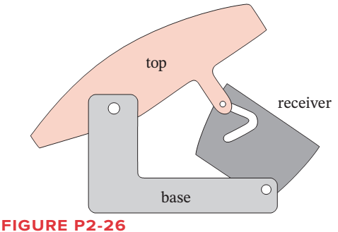
Ch. 2 - Use number synthesis to find all the possible link...Ch. 2 - Prob. 2.12PCh. 2 - Use linkage transformation to create a 1-DOF...Ch. 2 - Use linkage transformation to create a 1-DOF...Ch. 2 - Calculate the Grashof condition of the fourbar...Ch. 2 - Prob. 2.16PCh. 2 - Describe the difference between a cam-follower...Ch. 2 - Examine an automobile hood hinge mechanism of the...Ch. 2 - Find an adjustable arm desk lamp of the type shown...Ch. 2 - The torque-speed curve for a 1/8 hp permanent...Ch. 2 - Find the mobility of the mechanisms in Figure...Ch. 2 - Find the Grashof condition and Barker...Ch. 2 - Find the rotatability of each loop of the...Ch. 2 - Find the mobility of the mechanisms in Figure...Ch. 2 - Find the mobility of the ice tongs in Figure P2-6:...Ch. 2 - Prob. 2.26PCh. 2 - Prob. 2.27PCh. 2 - Find the mobility of the corkscrew in Figure P2-9.Ch. 2 - Figure P2-10 shows Watts sun and planet drive that...Ch. 2 - Figure P2-11 shows a bicycle handbrake lever...Ch. 2 - Figure P2-12 shows a bicycle brake caliper...Ch. 2 - Find the mobility, the Grashof condition, and the...Ch. 2 - The approximate torque-speed curve and its...Ch. 2 - Prob. 2.34PCh. 2 - Prob. 2.35PCh. 2 - Sketch the equivalent linkage for the cam and...Ch. 2 - Describe the motion of the following rides,...Ch. 2 - For the mechanism in Figure P2-1 a, number the...Ch. 2 - Repeat Problem 2-38 for Figure P2-1b.Ch. 2 - Repeat Problem 2-38 for Figure P2-1c.Ch. 2 - Prob. 2.41PCh. 2 - Find the mobility, the Grashof condition, and the...Ch. 2 - Find the mobility, the Grashof condition, and the...Ch. 2 - Figure P2-20 shows a Rube Goldberg mechanism that...Ch. 2 - All the eightbar linkages in Figure 2-11 part 2...Ch. 2 - Prob. 2.46PCh. 2 - Prob. 2.47PCh. 2 - Find the mobility of the mechanism shown in Figure...Ch. 2 - Find the mobility of the mechanism shown in Figure...Ch. 2 - Find the mobility of the mechanism shown in Figure...Ch. 2 - Find the mobility of the mechanism shown in Figure...Ch. 2 - Prob. 2.52PCh. 2 - Prob. 2.53PCh. 2 - Repeat Problem 2-38 for Figure P2-1f.Ch. 2 - Repeat Problem 2-38 for Figure P2-1g.Ch. 2 - For the example linkage shown in Figure 2-4 find...Ch. 2 - For the linkage shown in Figure 2-5b find the...Ch. 2 - Prob. 2.58PCh. 2 - Figure P2-21b shows a mechanism. Find its mobility...Ch. 2 - Prob. 2.60PCh. 2 - Figure P2-21 d shows a log transporter. Draw a...Ch. 2 - Figure P2-21e shows a plow mechanism attached to a...Ch. 2 - Figure P2-22 shows a Hart inversor sixbar linkage....Ch. 2 - Figure P2-23 shows the top view of the partially...Ch. 2 - Figure P2-24a shows the seat and seat-back of a...Ch. 2 - Figure P2-24b shows the mechanism used to extend...Ch. 2 - Figure P2-24b shows the mechanism used to extend...Ch. 2 - Figure P2-25 shows a sixbar linkage. Is it a Watt...Ch. 2 - Use number synthesis o find all the possible link...Ch. 2 - Use number synthesis to find all the possible link...Ch. 2 - Prob. 2.71PCh. 2 - For the mechanism in Figure P2-26, number the...Ch. 2 - Figure P2-27 shows a schematic of an exercise...Ch. 2 - Calculate the mobility of the linkage in Figure...Ch. 2 - Calculate the Grashof condition of the fourbar...Ch. 2 - The drum brake mechanism in Figure P2-4g is a...
Knowledge Booster


Learn more about
Need a deep-dive on the concept behind this application? Look no further. Learn more about this topic, mechanical-engineering and related others by exploring similar questions and additional content below.Similar questions
- Indicate the limbs with numbers and the joints with letters on the mechanism whose kinematic diagram is given below. Write the types of joints. Calculate the degrees of freedomarrow_forwardb) You are given a set of six links. The lengths of the links are as follows: 6.3cm, 9.1cm,12.4cm,15.6cm,20cm,40.2cmSketch a crank-rocker mechanism you can realize using a selection of four links from the set.arrow_forwardThe number of degrees of freedom of the linkage shown in the figure.arrow_forward
- can you solve 4-15?arrow_forwardHi I was wondering if I could get help with the last three parts in this question to find the instant centers of the linkagesarrow_forwardWrite and draw the following grashof's criterion and kind of grashof's four-bar mechanism such as; 1. Crank-rocker mechanism; 2. Drag link mechanism; 3. Double rocker mechanism; 4. Crossover-position or charge-point mechanism; 5 Triple rocker mechanism (non-grashof). Use technical Pen for the following: 0.2(light -for linkages and hand writing), 0.4(medium - for joints), 0.6(heavy - for fixed link or frames) use 2-4-4 template, all caps, italicized.arrow_forward
- solve 2 draw schematic diagramarrow_forwardFor each vector polygon in Figure P1-3, write the vector equation that gives the resultant R,just answer the 1Carrow_forwardCan someone draw grashof's mechanism: Crank-rocker Mechanism in ENGINEERING DRAWING FORMAT basing with the picture attached. Use Technical Pens for drawing: 0.2(light -for linkages and hand writing), 0.4(medium - for joints), 0.6(heavy - for fixed link or frames) Thank you!arrow_forward
- DRAW ONLY THE FBD OR FREE BODY DIAGRAM FOR THE GIVEN FIGURE. COMPLETE FBD WITH LABELS. WRITE LEGIBLY OR TYPEWRITTEN FOR UPVOTE. NO UPVOTE IF INCOMPLETEarrow_forwardplease draw the free body diagram and solve [handwriting only]arrow_forwardA hole is to be drilled as shown by the circle. Using the part geometry shown below, indicate on the part sketch where locator(s) should be positioned according to the 3-2-1 principle. Use dashed lines to indicate locators on hidden surfaces. Also indicate where clamping force(s) should be applied using arrows. Use the minimum number of clamping forces.arrow_forward
arrow_back_ios
SEE MORE QUESTIONS
arrow_forward_ios
Recommended textbooks for you
 Elements Of ElectromagneticsMechanical EngineeringISBN:9780190698614Author:Sadiku, Matthew N. O.Publisher:Oxford University Press
 Mechanics of Materials (10th Edition)Mechanical EngineeringISBN:9780134319650Author:Russell C. HibbelerPublisher:PEARSON
 Thermodynamics: An Engineering ApproachMechanical EngineeringISBN:9781259822674Author:Yunus A. Cengel Dr., Michael A. BolesPublisher:McGraw-Hill Education
 Control Systems EngineeringMechanical EngineeringISBN:9781118170519Author:Norman S. NisePublisher:WILEY
 Mechanics of Materials (MindTap Course List)Mechanical EngineeringISBN:9781337093347Author:Barry J. Goodno, James M. GerePublisher:Cengage Learning
 Engineering Mechanics: StaticsMechanical EngineeringISBN:9781118807330Author:James L. Meriam, L. G. Kraige, J. N. BoltonPublisher:WILEY
Elements Of Electromagnetics
Mechanical Engineering
ISBN:9780190698614
Author:Sadiku, Matthew N. O.
Publisher:Oxford University Press
Mechanics of Materials (10th Edition)
Mechanical Engineering
ISBN:9780134319650
Author:Russell C. Hibbeler
Publisher:PEARSON
Thermodynamics: An Engineering Approach
Mechanical Engineering
ISBN:9781259822674
Author:Yunus A. Cengel Dr., Michael A. Boles
Publisher:McGraw-Hill Education
Control Systems Engineering
Mechanical Engineering
ISBN:9781118170519
Author:Norman S. Nise
Publisher:WILEY
Mechanics of Materials (MindTap Course List)
Mechanical Engineering
ISBN:9781337093347
Author:Barry J. Goodno, James M. Gere
Publisher:Cengage Learning
Engineering Mechanics: Statics
Mechanical Engineering
ISBN:9781118807330
Author:James L. Meriam, L. G. Kraige, J. N. Bolton
Publisher:WILEY
Ch 2 - 2.2.2 Forced Undamped Oscillation; Author: Benjamin Drew;https://www.youtube.com/watch?v=6Tb7Rx-bCWE;License: Standard youtube license