
Concept explainers
Videos
Consider the circuit in Figure P2.62. The output of a diode AND logic gate is connected to the input of a second diode AND logic gate. Assume
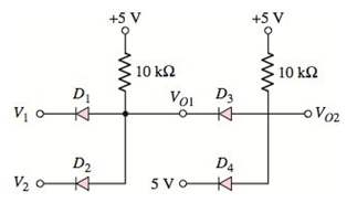
Figure P2.62
(a)
Values of output voltages
Answer to Problem 2.62P
The values of output voltages are
The values of output voltages are
The values of output voltages are
Explanation of Solution
Given:
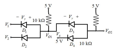
The given circuit is shown below.
Voltages given:
Calculation:
(i) Assume voltage
The entire circuit can be divided into two parts.
Now considering the first part,
On considering the connection of Diodes it is known that diodes are connected in reverse bias.
So, taking considerations from the first part, it is concluded that the output,
Hence, if the inputs of circuit are
Similarly, if the inputs of circuit are
Similarly, if the inputs of circuit are
Similarly, if the inputs of circuit are
Let’s make the truth table for
Table 1
| 0 0 5 5 | 0 5 0 | 0 0 0 5 |
On considering, the Boolean expression for
Now, taking considerations from the second part, as diodes are connected in reverse bias it is concluded that if any one of the inputs,
So the expression for the output voltage
Now for the given inputs
The diodes
Hence, from the expression for ideal diode output voltages are
(ii) Let’s assume voltage
The entire circuit can be divided into two parts.
Now considering the first part,
On considering the connection of Diodes it is known that diodes are connected in reverse bias.
So, taking considerations from the first part, it is concluded that the output,
Hence, if the inputs of circuit are
Similarly, if the inputs of circuit are
Similarly, if the inputs of circuit are
Similarly, if the inputs of circuit are
Let’s make the truth table for
Table 1
| 0 0 5 | 0 5 0 5 | 0 0 0 5 |
On considering, the Boolean expression for
Now, taking considerations from the second part, as diodes are connected in reverse bias it is concluded that if any one of the inputs,
So the expression for the output voltage
Now for the given inputs,
The diodes
Calculating the value of output voltage,
Calculating the value of output voltage,
Hence, output voltages are
(iii) Let’s assume voltage
The entire circuit can be divided into two parts.
Now considering the first part,
On considering the connection of Diodes it is known that diodes are connected in reverse bias.
So, taking considerations from the first part, it is concluded that the output,
Hence, if the inputs of circuit are
Similarly, if the inputs of circuit are
Similarly, if the inputs of circuit are
Similarly, if the inputs of circuit are
Let’s make the truth table for
Table 1
| 0 0 5 5 | 0 5 0 5 | 0 0 0 5 |
On considering, the Boolean expression for
Now, taking considerations from the second part, as diodes are connected in reverse bias it is concluded that if any one of the inputs,
So the expression for the output voltage
Now for the given inputs
The diodes
Calculating the value of output voltage,
Calculating the value of output voltage,
Hence, output voltages are
Therefore, in their LOW states the value of
(b)
Relative values of VO1 and VO2 in their “low” state
Answer to Problem 2.62P
Logic “0” signal degrades as it goes through additional logic gates.
Explanation of Solution
Given:
The given circuit is shown below.

Circuit diagram:

Logic “0” signal degrades as it goes through additional logic gates.
The diodes
Calculating the value of output voltage,
Calculating the value of output voltage,
Hence, output voltages are
Want to see more full solutions like this?
Chapter 2 Solutions
MICROELECT. CIRCUIT ANALYSIS&DESIGN (LL)


- How is a solid-state diode tested? Explain.arrow_forwardIn the circuit shown, a 5 V Zener diode is used to regulate the voltage across load Ro The input is an unregulated DC voltage with a minimum value of 6 V and a maximum value of 8 V. The value of R, is 6 2. The Zener diode has a maximum rated power dissipation of 2.5 W, Assuming the Zener diode to be ideal, the minimum value of Ro is 52. wwww R₂arrow_forwardConsider the circuit with three diodes and a AC input, as shown below: D2 R1 D1 D3 R2 Assume that the input AC voltage is Ttsin(100TTT). You may consider the diodes to be ideal. mean voltage generated across resistor R2 is (assuming current direction to be from AC so into R1, through diode network, and through R2 from top to bottom): O a. 0.5V Ob. -0.5V O c. 1V O d. OVarrow_forward
- You are asked to design a Zener diode voltage regulator, as shown in Figure 1.e, tỏ have a stabilized voltage of 3.3 V across the load R,. The Zener diode has a constant voltage of 3.3 V when its current is more than a minimum current of 10 mA and has negligible dynamic resistance. The load current changes between 0 mA (open circuit) and 200 mA. The input voltage Vị is equal to 5 V. Choose the value of series resistance Rs to have stabilized voltage at the output at all conditions. ii) Calculate the maximum current in the diode and the resistor Re. Based on these values, choose the maximum power ratings of the diode and the resistor Rs RL Rsarrow_forward(a) Calculate and sketch the output voltage Vo given the input voltage graph Vi as shown in Figure Q2(a). Assume the diode is Silicon. 20 Vo -10 3V Figure Q2(a) (b) For the Zener diode configuration given in Figure Q2(b), i determine the minimum value of R, and I, that will result in VRz being maintained at 8 V. calculate the maximum value of R1 based on the given maximum zener current, 1. IzM, so that the zener can operate in safe range. 5 kQ Iz V;=8 V IzM=1 mA Vi= 20 V Figure Q2(b)arrow_forwardQ2:- Find the level of Vo for each circuit shown in the Figure below. Also, determine the status of each diode; if it is forward or reverses biasing. Assume all diodes are silicone with 0.7v drop. +5 V +15 V -10 V (12 Marks) R DI +5 VoK D +5 VoK DI -5 VoH -5 Vo4 D2 D2 D2 +5 VoH D3 +5 Vo4 D3 -10 VoK D4 V. -5 Vo K (a) (b)arrow_forward
- Q1/ a/Draw the output voltage waveform for the bridge rectifier in this figure : D D4 120 V ms D D2 R3 Vout B/ What PIV rating is required for the diodes in a bridge rectifier that produces an average output voltage of 50 V? Q2/ Determine the minimum input voltage required for regulation to be established in the figure. Assume an ideal zener diode with IzK = 1.5 mA and Vz= 14 V. R 560 N VINarrow_forwardQ1 Assume that each diode has a turn-on voltage 0.7V in the circuit shown in Figure Q1. By using the constant voltage drop model: 1kN D1 D2 2kN 4k2 6V 3V 4V Figure Q1 a) Show that it is not possible that D1 is on and D2 is off. (Hint: show a contradiction) b) Show that both D1 and D2 are on.arrow_forwardHow do I calculate the dynamic resistance of a zener diode with the following set of values given please? The circuit in figure is the circuit in question I am trying to solve this for please. Vin(DC) = 10V vin(ac) = 0.05sin(wt) Vz(voltage of diode) = 4.5V R1 = 1000 ohmsarrow_forward
- Vps = 10 V R = 0.1k02 ww -ovo R₁. Consider the Zener diode circuit shown in figure. The Zener diode voltage is Vz= 5.8V at Iz= 10mA and the Zener resistance is rz = 200. a) Find the output voltage for RL = 1k0 b) Find the change in the output voltage when the load resistance varies +ARL.arrow_forwardAnalyse the voltage waveforms of the input, Vị and the output, V, for a clamper circuit shown in Figure Q3(b)(i) and Figure Q3(b)(ii). V. V. 10 V 3 V -10 -17 (i) (ii) Figure Q3(b) If the ideal diode is replaced with a silicon diode, explain the changes of the output voltage measurement.arrow_forwardDraw the input waveform and output waveform for the circuit given below with proper values marked in the figure. Assume D1 as germanium and D2 as silicon diodes. Input Vpp%3D20V, V1=3 V and V2=10 V. R D2 D1 Vin Vout V1 V2 Maximum voltage of output waveform Minimum voltage of output waveform Psarrow_forward
